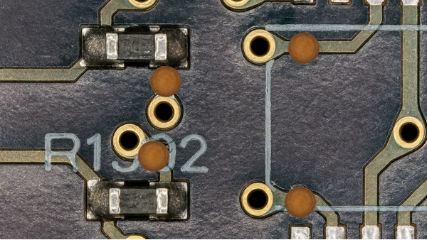
A customer recently identified a design error on the secondary side of a circuit board involving two misrouted component patterns. This error affected two circuit paths, necessitating corrective action. While many boards had already been fully assembled, a significant portion remained partially assembled, leaving the affected site unpopulated and accessible.
Two rework methods were developed to address the issue, each tailored to the specific assembly stage of the board.
Option 1: Jumper Wire Rework for Fully Assembled Boards
The most efficient solution for boards already in their final assembled state involved reworking the circuit using insulated jumper wires. The process began by removing the affected component, a 14-pin gull-wing device, and performing four precise circuit trace cuts. (See Figure 1)
After these modifications, the component was reinstalled, and jumper wires were carefully soldered to establish the correct electrical connections. This method provided a practical and effective path to restore circuit integrity on completed boards.
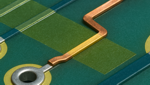
Option 2: Surface Conductor Correction for Partially Assembled Boards
A more streamlined and permanent solution was applied to partially assembled boards. In these cases, flat ribbon conductors were installed directly on the board surface to reroute the circuits properly. Once in place, these conductors were secured and electrically insulated with a thermoset epoxy overcoat, ensuring long-term reliability (See Figure 2).
This approach allowed the boards to complete final assembly without requiring additional post-assembly rework, improving efficiency and throughput.
Several members of the Circuit Technology Center team contributed to this feature story. Images may be altered or recreated to protect proprietary information.