In the world of circuit board assembly, adding jumper wires is often unavoidable. Whether you're refining a prototype, modifying a finished design, or correcting a defect, jumper wires serve as a practical solution when changes must be made after manufacturing. But while jumper wires can be helpful, they must be applied with care and precision.
Broadly, jumper wires fall into three categories:
- Design-Integrated Jumper Wires
These are part of the original design. Their placement, routing, and bonding should be documented in the engineering drawings or instructions.
- Post-Design Modifications
These are added after fabrication to implement design changes. They should be supported by engineering change notices or updated documentation.
- Defect Corrections
These are used to fix errors or faults in the board, and while they might be last-minute fixes, they should still follow solid workmanship practices.
While jumper wire procedures can be complex and situation-specific, here are some foundational best practices you can rely on:
- Locate on the Component Side
When possible, place jumper wires on the component side of the board, especially if that side contains most of the larger components. This aligns with the principle that jumper wires are effectively treated as components in their own right.
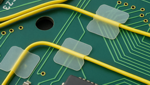
- Use Clean, Direct Routing
Route jumper wires in an X-Y path with minimal bends. Straight, organized runs aren't just easier to trace—they’re also more reliable and save material.
- Maintain Low Profiles
Jumper wires should sit no more than 3.2 mm (0.125") above the board. Avoid running them over components or leads that might interfere with installation or operation.
- Limit Bare Conductor Lengths
Bare jumper wires should be kept shorter than 12.7 mm (0.50"). Longer bare runs increase the risk of shorts or damage. And remember: even short bare wires must not violate minimum electrical clearances.
- Avoid Crossing Pads or Vias
Don’t route jumper wires over unused pads or vias, especially test points. If there's no alternative, leave enough slack so wires can be moved if components are later installed. Once placed, jumper wires should be disturbed as little as possible.
- Stay Clear of Component Leads and Heat Sinks
Routing under or over component leads or bodies complicates future rework and could block access. Contact with heat sinks should also be avoided—they can melt insulation and cause shorts.
- Add Stress Relief
All materials on a circuit board are affected by thermal expansion and mechanical stress. A small loop or slack near the termination point allows movement without strain. Avoid tight bends—use a bend radius at least 3× the wire diameter.
When Jumper Wires Must Pass Through the Board
In cases where a jumper must go from one side of the board to the other, it's acceptable to use a plated through-hole, provided the wire is insulated and a sleeve is inserted into the hole for added protection. Alternatively, a carefully drilled hole can be used, but make sure you don’t interfere with existing traces or internal layers.
Soldering Tips
If a jumper wire is soldered into a plated hole, the connection should be visible on the opposite side, just like with any standard through-hole lead. Wires soldered to lifted or clipped leads must be fully insulated to avoid shorts.
Jumper wires may be terminated using various methods depending on the application. For detailed instructions and diagrams, refer to our related guides below.
Several members of the Circuit Technology Center team contributed to this feature story. Images may be altered or recreated to protect proprietary information.