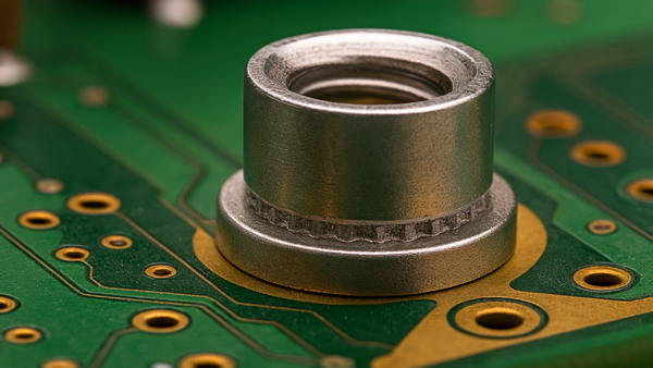
For this repair, we're looking at correcting baseboard damage or addressing a design error at an ejector handle location. See Image 1. Card ejector handles are often held in place using a pin pressed into a non-plated hole on the circuit board. This is a relatively old circuit board mating method, but we occasionally encounter this issue.
When the ejector handle is retracted, the lever action ejects the circuit board from the card cage. With this action, the ejector handle roll pin will put considerable stress on the ejector handle mounting hole. Standard circuit board construction will easily withstand this stress, but what about a modified or repaired mounting hole location?
There are a few repair processes used to repair or modify a non-plated hole location on circuit boards. A standard epoxy fill process is often employed for mounting holes or alignment holes where the "extra strength" is not required. See: 3.3.1 Hole Repair, Epoxy Method
A second procedure uses replacement board material, instead of epoxy alone to provide added strength for those applications where "extra strength" is a critical requirement. See: 3.3.2 Hole Repair, Transplant Method
The following is a refinement of the transplant procedure to optimize the results and achieve the highest strength.
- Drill out holes using a milling machine. Ensure holes are drilled in the center by using data points. Pin the circuit board on the table of a milling machine. See Image 2.
- Inspect the holes carefully. Hole walls must be smooth and clear of debris.
- Seal the bottom surface of the board with high-temperature tape. This will prevent epoxy leakage and avoid air entrapment when the epoxy-coated dowel is placed in the hole from the top side of the board.
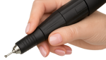
- Apply epoxy to the dowel plug and the hole wall. See Image 3.
- Insert the dowel into the hole. Ensure the dowel plug is inserted evenly and the epoxy is present around the entire hole circumference.
- Bake the board as required to cure the epoxy fully.
- Remove the high-temperature tape and inspect for voids in the epoxy. If present, grind out the defects, re-epoxy, and re-bake boards.
- Ensure the top and bottom surfaces of the dowel are level with the board surface, and machine if needed. See Image 4.
- Drill the finished hole at the specified location. See Image 5.
This repair process is an extra-strength repair capable of withstanding the typical forces applied to a standard circuit board.
Several members of the Circuit Technology Center team contributed to this feature story. Images may be altered or recreated to protect proprietary information.