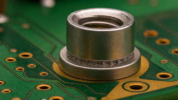
Press-in fasteners are a simple yet essential element of printed circuit assembly. They are self-clinching fasteners that permit the mounting of heavy structures onto relatively thin circuit board substrates. (See Figure 1)
When properly installed, they provide a sturdy solution to various chassis, heat sinks, stiffeners, and other hardware mounting demands.
The potential problem with press-in fasteners is in their mounting. The end with teeth is fitted by force into a hole that is smaller than the circumference of the teeth. That is what provides the grip of the fastener on the substrate. Forced insertion deforms the hole into which the press-in fastener is mounted, which is fine if that is what the hole was designed for, and in the vast majority of cases, that is precisely what happens.
However, in an industry that manufactures millions of assemblies a year, it is guaranteed that there will be errors in manufacture and that some of them will be related to improper press-in fastener insertion.
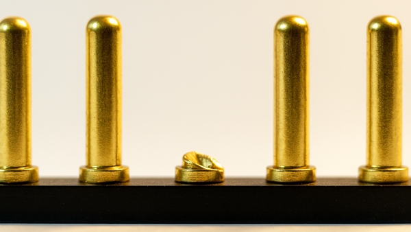
Unfortunately, a lot of crazy things can happen. For example, the wrong press-in fastener is inserted, the correct press-in fastener is inserted in the wrong hole, or the correct press-in fastener is inserted improperly. Any of these events can cause unacceptable damage to an assembly.
At Circuit Technology Center, we see more than our fair share of these problems. In one case, a customer mistakenly inserted a press-in fastener in the wrong hole. They quickly realized their mistake and removed the press-in fasteners from the holes, but the damage was already done.
The good news is, this type of damage can be repaired. The alert customer sent the boards to us for evaluation. Our engineering staff evaluated the boards and determined there was no damage to internal circuitry or nearby power and ground planes, which was confirmed by the customer's test data.
So the remaining challenge was to repair the assembly. What's the best way to do this? With all the technological advances in this industry, you may think that the "old-fashioned" eyelet is a thing of the past. But eyelets are still frequently used, and this is a perfect situation to use them. Here's how it's done.
The laminate damage was milled out slightly oversized using a milling machine. A FR4 dowel of laminate was bonded into the milled holes using high-strength, thermo-set epoxy. After curing, the excess material was machined flush with the circuit board surface.
The next step involved repositioning the circuit board on the milling machine to locate the proper-sized clearance hole for a new press-in fastener in the precise position required. Finally, a qualified technician used a calibrated arbor press to insert the new fastener.
Several members of the Circuit Technology Center team contributed to this feature story. Images may be altered or recreated to protect proprietary information.