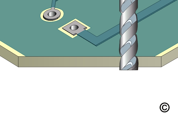
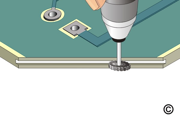
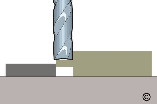
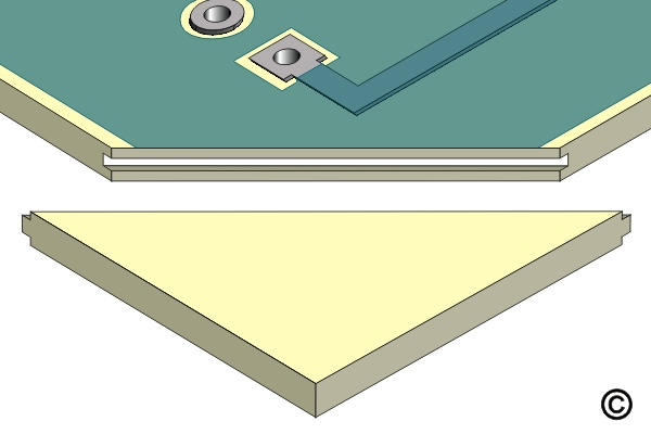
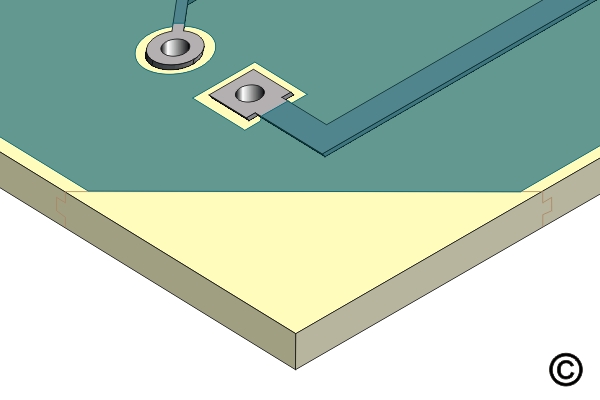
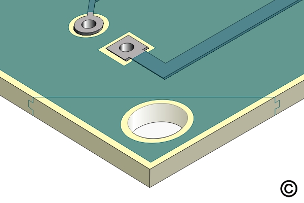
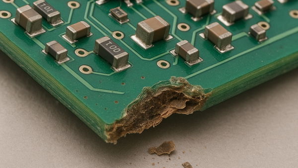
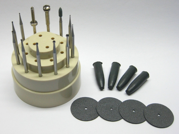
3.5.3 Base Material Repair, Edge Transplant Method
Outline
This procedure is used to repair mechanical or thermal damage to circuit board base material. This method is used when extended areas of base material must be completely replaced. This method may be used on single-sided, double-sided, or multilayer circuit boards or assemblies.
Caution: Surface circuits may need to be replaced in the damaged area. Be sure that the appropriate circuit diagrams or photographs reflecting the original circuits are available so that they may be replaced after repairing the base board material. Damage to internal circuits or planes may have to be restored using surface wires.
Minimum Skill Level - Expert
Recommended for technicians with advanced soldering and component rework skills and extensive experience in most repair/rework procedures.
Conformance Level - High
This procedure most closely duplicates the physical characteristics of the original, and most probably complies with all the functional, environmental and serviceability factors.
Microscope
Precision microscope with stand and lighting for work and inspection.
Micro Drill System
Versatile power tool for milling, drilling, grinding, cutting and sanding circuit boards.
Milling Machine
Use for precision milling of circuit board materials.
Oven
General purpose oven for drying, baking and curing epoxies.
Precision Drill
Precision drill press for accuracy and controlled depth drilling.
Scraper
Hardened stainless steel tip for scraping solder mask and removing defects.
Wipes
Nonabrasive, low-linting wipes for cleanup.
Images and Figures
Damaged Base Material
Figure 1: Cut away damaged base material with a saw or milling cutter.
Figure 2: Cut a groove into the edge of the circuit board.
Figure 3: Mill a tongue onto the edge of the replacement base material.
Figure 4: Check fit of new base material. The tongue must mate with the groove in circuit board.
Figure 5: Trim the excess material with a saw or milling cutter.
Figure 6: Complete the repair by drilling holes and applying coatings as required.
Procedure
Clean the area.
Cut away the damaged board material using the Saw or milling cutter. Remove all evidence of the damaged material. No fibers of laminate material should be exposed. File the edge to ensure that the edge is flat. (See Figure 1)
Caution: Exercise care to avoid damage to any internal conductors. If any internal conductors are damaged, surface wires may be required to restore the electrical connection.
Clean the area.
Install a carbide saw into the Micro-Drill System. Set the speed to maximum and machine a groove in the edge of the circuit board where the new base material will be installed. The groove must be centered on the edge to ensure that the new piece will fit properly. The groove width should be approximately 1/3 of the PC board thickness. The groove depth should be approximately double the groove width. (See Figure 2)
Cut a piece of replacement base board material that is the same thickness and type as the piece removed. The replacement piece may be oversized, the excess material will be removed after the replacement piece has been epoxied in place.
Install an end mill into the chuck of a milling machine. Machine a tongue onto the entire mating edge of the replacement base material. The dimensions of the tongue should match the size of the milled groove. (See Figure 3)
Where required, apply High-Temperature Tape to protect exposed parts of the circuit board bordering the prepared area.
Check the fit to be sure the new base material properly mates with the groove in the circuit board. (See Figure 4)
Mix the epoxy.
Coat both the tongue and groove surfaces with epoxy and fit together. Remove excess epoxy.
Cure the epoxy per Procedure 2.7 Epoxy Mixing and Handling.
After the epoxy has cured, remove the High-Temperature Tape.
If needed, scrape off any excess epoxy using the knife or scraper.
Note: If needed, apply an additional thin coating to seal any scraped areas.
Saw or mill off excess base material and file flush with the existing edge. (See Figure 5)
Clean the area.
Complete by drilling holes, slots, etc., or adding circuitry as required. (See Figure 6)
If needed, replace solder mask or conformal coating. (See Figure 6)
Evaluation
Dimensions of area replaced should be checked to conform to specifications required.