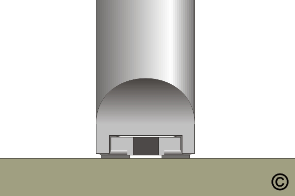
8.2.1 Component Removal, Surface Mount Chip Components, Forked Tip Method
Remove surface mount chip components using forked tip soldering tools. Learn balanced heating and lifting techniques to avoid pad lifting or laminate damage.
Minimum Skill Level: Intermediate
Conformance Level: High
REQUEST FOR QUOTE GUIDES INDEX