Outline
This procedure includes figures and tables for solder joint acceptability criteria on a variety of component types.
Minimum Skill Level - Intermediate
Recommended for technicians with skills in basic soldering and component rework, but may be inexperienced in general repair/rework procedures.| Procedure References | |
| 1-0 | 1.0 Foreword |
| 7-1-1 | 7.1.1 Soldering Basics |
Procedure
Figure 1: Dimensional Criteria for Through-Hole Components
|
Table 1: Acceptable Solder Criteria for Through-Hole Components
| Feature | Dim | Class 1 | Class 2 | Class 3 |
| Circular wetting of the solder of the lead and plated hole barrel on the component side. | 1 | Not Specified | 180 deg | 270 deg |
| Plated hole fill. | 2 | Not Specified | 75% | 75% |
| Circular fillet and wetting of the solder of the lead and plated hole barrel on the solder side. | 1 | 270 deg | 270 deg | 330 deg |
| Percent of the land area covered with solder on the component side. | 3 | 0 | 0 | 0 |
| Percent of the land area covered with solder on the solder side. | 4 | 75% | 75% | 75% |
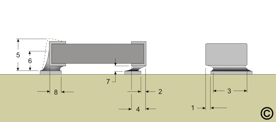
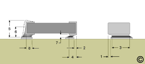
Figure 2: Dimensional Criteria for Chip Components
|
Table 2: Acceptable Solder Criteria for Chip Components
| Feature | Dim | Class 1 | Class 2 | Class 3 |
| Maximum Component Side Overhang | 1 | Less than 50% of the component termination width or 50% of the pad width, whichever is less. | Less than 50% of the component termination width or 50% of the pad width, whichever is less. | Less than 25% of the component termination width or 25% of the pad width, whichever is less. |
| Maximum Component End Overhang | 2 | Not permitted. | Not permitted. | Not permitted. |
| Minimum End Joint Width | 3 | 50% of the component termination width or 50% of the pad width, whichever is less. | 50% of the component termination width or 50% of the pad width, whichever is less. | 75% of the component termination width or 75% of the pad width, whichever is less. |
| Minimum Side Joint Length | 4 | Evidence of proper wetting. | Evidence of proper wetting. | Evidence of proper wetting. |
| Maximum Fillet Height | 5 | Solder may overhang the pad but must not touch the non-soldered portion of the component package body. | Solder may overhang the pad but must not touch the non-soldered portion of the component package body. | Solder may overhang the pad but must not touch the non-soldered portion of the component package body. |
| Minimum Fillet Height | 6 | Evidence of proper wetting. | Evidence of proper wetting. | Equal to the solder thickness plus 25%, or equal to the solder thickness plus 0.50 mm (.020"), whichever is less. |
| Minimum Solder Thickness | 7 | Evidence of proper wetting. | Evidence of proper wetting. | Evidence of proper wetting. |
| Minimum End Overlap | 8 | Evidence of any overlap is required. | Evidence of any overlap is required. | Minimum 25% of the termination length. |
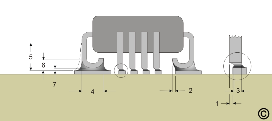
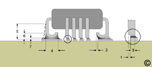
Figure 3: Dimensional Criteria for J Lead Components
|
Table 3: Acceptable Solder Criteria for J Lead Components
| Feature | Dim | Class 1 | Class 2 | Class 3 |
| Maximum Lead Side Overhang | 1 | No more than 50% of the lead width. | No more than 50% of the lead width. | No more than 25% of the lead width. |
| Maximum Lead Toe Overhang | 2 | Not specified. | Not specified. | Not specified. |
| Minimum Lead End Joint Width | 3 | 50% of the lead width. | 50% of the lead width. | 75% of the lead width. |
| Minimum Side Joint Length | 4 | Evidence of proper wetting. | Side joint length must exceed 150% of the lead width. | Side joint length must exceed 150% of the lead width. |
| Maximum Fillet Height | 5 | No maximum, but solder must not touch the component package body. | No maximum, but solder must not touch the component package body. | No maximum, but solder must not touch the component package body. |
| Minimum Heel Fillet Height | 6 | Equal to the solder thickness plus 50% of the lead thickness. | Equal to the solder thickness plus the lead thickness. | Equal to the solder thickness plus the lead thickness. |
| Minimum Solder Thickness | 7 | Evidence of proper wetting. | Evidence of proper wetting. | Evidence of proper wetting. |
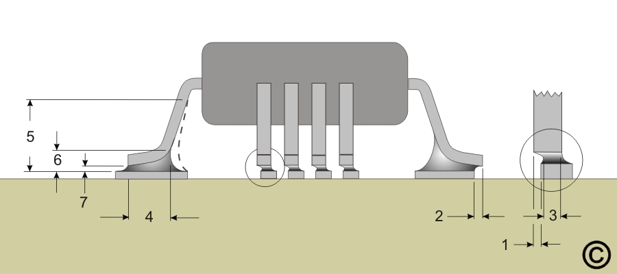
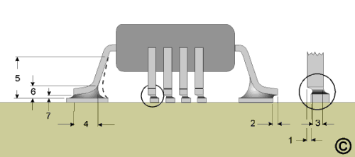
Figure 4: Dimensional Criteria for Gull Wing Components
|
Table 4: Acceptable Solder Criteria for Gull Wing Components
| Feature | Dim | Class 1 | Class 2 | Class 3 |
| Maximum Lead Side Overhang | 1 | No more than 50% of the lead width or 0.50 mm (.020"), whichever is less. | No more than 50% of the lead width or 0.50 mm (.020"), whichever is less. | No more than 25% of the lead width or 0.50 mm (.020"), whichever is less. |
| Maximum Toe Overhang | 2 | Does not violate minimum electrical clearance. | Not acceptable. | Not acceptable. |
| Minimum End Joint Width | 3 | 50% of the lead width. | 50% of the lead width. | 75% of the lead width. |
| Minimum Side Joint Length: Lead thickness greater than 3X lead width | 4 | Equal to the lead width or 0.50 mm (.020"), whichever is less. | 3 times the formed foot length or 75% of the formed foot length, whichever is longer. | 3 times the formed foot length or 75% of the formed foot length, whichever is longer. |
| Minimum Side Joint Length: Lead thickness less than 3X lead width | 4 | Equal to the lead width or 0.50 mm (.020"), whichever is less. | Equal to 100% of the formed foot length. | Equal to 100% of the formed foot length. |
| Maximum Heel Fillet Height | 5 | No maximum, but solder must not touch the component package body. | No maximum, but solder must not touch the component package body. | No maximum, but solder must not touch the component package body. |
| Minimum Heel Fillet Height | 6 | Evidence of proper wetting. | Equal to the solder thickness plus 50% of lead thickness. | Equal to the solder thickness plus 100% of lead thickness. |
| Solder Thickness | 7 | Evidence of proper wetting. | Evidence of proper wetting. | Evidence of proper wetting. |
Images
Solder Joint Acceptance Criteria
Dimensional Criteria for Through Hole Components
Dimensional Criteria for Chip Components
Dimensional Criteria for J Lead Components
Dimensional Criteria for Gull Wing Components