|
Outline
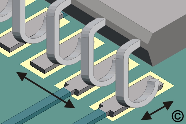
This procedure covers the general guidelines for soldering surface mount J lead components. There is basically only one style of J lead component. Whether leads are on two sides or four sides, or whether the component is large or small, the soldering principles are the same.
|
|||||||||||||||||||||||||||
|
Procedure
Procedure
|
|||||||||||||||||||||||||||
Images and Figures
Soldering Surface Mount J Lead Components, Point To Point Method

Figure 1. Place component and check alignment.

Figure 2. Place the soldering iron tip at the junction between the pad and component lead.
|
|||||||||||||||||||||||||||
7.4.1 Soldering Surface Mount J Lead Components, Point To Point Method
Procedure covers soldering of surface mount J lead components on circuit board assemblies using a point to point soldering method.
Minimum Skill Level: Intermediate
Conformance Level: High
REQUEST FOR QUOTE GUIDES INDEX

Soldering Surface Mount J Lead Components, Point To Point Method

Place component and check alignment.

Place the soldering iron tip at the junction between the pad and component lead.

Do you need help with surface mount and through-hole component rework or salvage?
LEARN MORE
SLIDESHOW STARTING
❮
❯


