Outline
This procedure covers the general guidelines for soldering surface-mount chip components. This procedure covers the following surface-mount chip components. While all of these components are different, the techniques for soldering are relatively similar.
Chip Resistors
The component body of chip resistors is made of alumina, a highly durable, white-colored material. The resistive material is typically located on the top. Chip resistors are usually mounted with the resistive element facing upwards to help dissipate heat.
Ceramic Capacitors
These components are constructed from several layers of ceramic with internal metalized layers. Because metal heats up much faster than ceramic, ceramic capacitors must be heated slowly to prevent internal separations between the ceramic and metal layers. Internal damage will generally not be visible, as any cracks will be located within the ceramic body of the component. Avoid rapid heating of ceramic chip capacitors during soldering operations.
Tantalum Capacitors
These capacitors are electrolytic devices that use a sintered tantalum anode and a thin oxide dielectric to achieve high capacitance in a small volume. They offer excellent stability, reliability, and low leakage current, making them a common choice in compact and high-performance electronics, such as medical devices, military systems, and communication equipment. Available in both solid and wet electrolyte versions, solid tantalum capacitors, particularly those using manganese dioxide or conductive polymer cathodes, are favored for their long service life and consistent electrical characteristics.
When hand-soldering tantalum capacitors, care must be taken to avoid rapid or excessive heating. A sudden temperature rise can cause the encapsulation to crack, damage the oxide dielectric, or degrade the cathode material, resulting in leakage or catastrophic failure. To prevent heat-related damage, the soldering temperature should be kept below 260°C (500°F), and the contact time should be limited to just a few seconds. Preheating the assembly and avoiding direct heat on the capacitor body helps reduce thermal stress and preserve component reliability.
Plastic Body
Another style of chip component has a molded plastic body that protects the internal circuitry. There are several types of components that share this exterior package design. The termination styles for plastic chip component packages vary considerably.
MELF
Metal Electrode Face cylindrical components. These may be capacitors, resistors, and diodes. It can be challenging to distinguish them apart, as there are no universal color codes or component designators printed on the component bodies.
Minimum Skill Level - Intermediate
Recommended for technicians with skills in basic soldering and component rework, but may be inexperienced in general repair/rework procedures.Conformance Level - High
This procedure most closely duplicates the physical characteristics of the original, and most probably complies with all the functional, environmental and serviceability factors.| Procedure References | |
| 1-0 | 1.0 Foreword |
| 2-1 | 2.1 Handling Electronic Assemblies |
| 2-2 | 2.2 Cleaning Procedures |
| 2-5 | 2.5 Baking and Preheating |
| 7-1-1 | 7.1.1 Soldering Basics |
| 7-1-2 | 7.1.2 Preparation For Soldering And Component Removal |
| 7-1-3 | 7.1.3 Solder Joint Acceptance Criteria |
Tools and Materials

General purpose cleaner for removing contamination. |

Sturdy rack for PCBs used for rework and positioning. |

Temperature adjustable heated plate to pre-heat components and circuit boards prior to tinning and reflow. |

Precision microscope with stand and lighting for work and inspection. |

Nine precision-crafted tools for detailed circuit board work. |

Properly maintained soldering iron and properly sized soldering iron tips. |

Training kit to practice circuit board soldering skills prior to testing for certification. |

Multiple sizes and tip configurations of tweezers for various small parts handling needs. |

Nonabrasive, low-linting wipes for cleanup. |
Procedure
Preparation for Tantalum and Ceramic Capacitors
- Set the hot plate to between 100°C and 125°C (212°F to 257°F). This temperature range warms the capacitors enough to reduce thermal shock during soldering but stays well below the threshold that could degrade internal materials.
- Place the capacitors on the plate for between 60 and 90 seconds. This is long enough for them to reach a uniform, moderate temperature. Do not leave the capacitors on the hot plate longer than 90 seconds.
- Use clean, insulated tweezers to handle the capacitors. Do not touch the terminations or body directly with bare fingers, and do not exceed 150°C (302°F) at any point during preheating.
- After preheating, immediately place the component on the prepared circuit board and solder it within 3–5 seconds per terminal, using a tip temperature no higher than 260°C (500°F).
Soldering Procedure
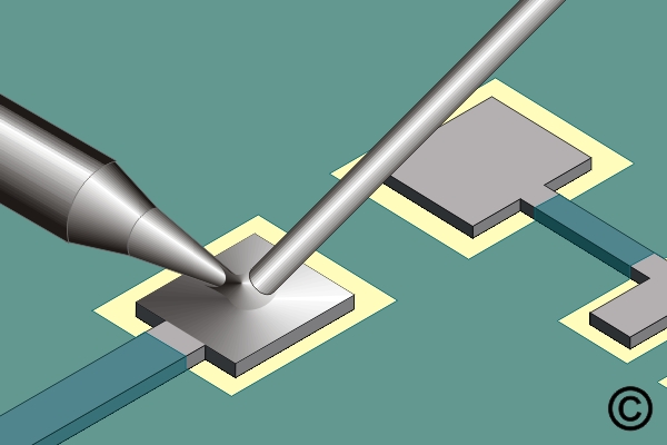
- Add liquid flux to one pad.
- Prefill one pad with solder. (See Figure 1)
- Clean the area.
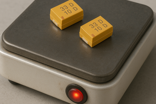
- See Preparation for Tantalum and Ceramic Capacitors for soldering these component types. (See Figure 2)
- Add liquid flux to both pads.
- Place the component in position and hold it steady with a wooden stick or tweezers to prevent the soldering iron from pushing the component out of alignment.
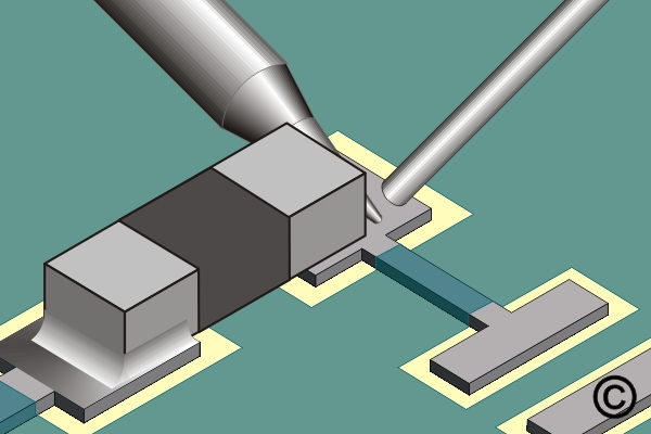
- Place the soldering iron tip at the junction between the prefilled pad and component lead. Flow the solder until the component drops into position and is securely soldered. Apply additional solder as needed. (See Figure 3)
- Remove the tip. Wait a moment for the solder to solidify before soldering the other side of the component. (See Figure 4)
- Clean, if required, and inspect.
Images