Abstract
Jumper wires play a critical role in circuit board assemblies, whether used as part of the original design, for modifications, or to correct defects. To ensure the integrity and reliability of these connections, engineers must adhere to specific guidelines when working with jumper wires. This paper presents ten essential rules for effectively attaching and routing jumper wires on circuit board assemblies, ensuring they are secure, organized, and compliant with industry standards.
Introduction
Jumper wires are indispensable in electronics design and assembly, serving various purposes, from planned connections to emergency repairs. This white paper outlines general guidelines for attaching and routing jumper wires to optimize the performance and reliability of circuit board assemblies.
Categories of Jumper Wires
Jumper wires can be categorized into three distinct types, each serving specific purposes:
- Component Jumper Wires: Integral parts of the original design, requiring documentation of routing, termination, and bonding through engineering instructions or drawing notations.
- Modification Jumper Wires: Added after design and fabrication to implement changes, necessitating proper documentation through engineering change notice instructions or drawing notations.
- Defect Correction Jumper Wires: Added to rectify defects in the circuit board assembly.
Ten Rules for Jumper Wires
This section presents ten essential rules to be followed when working with jumper wires, along with explanations for each rule:
- Placement on Component Side
Jumper wires should be placed on the component side of the circuit board assembly whenever possible.
Rationale: As jumper wires are considered components, locating them on the side with the majority of large components enhances assembly organization and reliability.
- Direct X-Y Routing
Jumper wires should be routed in an X-Y manner with minimal bends.
Rationale: Direct routing simplifies the layout, reduces material usage, and enhances reliability.
- Height Limitation
Jumper wires should not be raised more than 3.2 mm (0.125") above the board surface, avoiding interference with circuit board mounting or potential damage.
Rationale: Limiting the height minimizes the risk of physical damage or interference.
- Maximum Bare Conductor Length
Bare conductor jumper wires longer than 12.7 mm (0.50") should not be used. Bare conductor jumper wires shorter than 12.7 mm (0.50") should comply with minimum electrical clearance.
Rationale: Adhering to length limitations ensures electrical safety and proper signal transmission.
- Avoidance of Unused Pads and Test Points
Jumper wires should not cross unused component lands or pads, unless unavoidable due to layout constraints. Sufficient slack should be provided to allow the jumper wire to move if components need to be added later. Jumper wires should not pass over test points.
Rationale: Preventing interference with unused components and test points facilitates future rework and reduces the risk of accidental shorts.
- No Routing Over Components or Leads
Jumper wires should not be routed over component leads, bodies, or heat sinks.
Rationale: Unobstructed access to components is essential for effective rework, and heat sinks can melt wire insulation, leading to shorts.
- Stress Relief and Bend Radius
Jumper wires should include stress-relief features to accommodate thermal expansion and mechanical stress. Avoid tight bends, ensuring the minimum bend radius is at least 3 times the conductor diameter.
Rationale: Stress relief and appropriate bend radius prevent mechanical failures and signal degradation.
- Routing Through Plated Through-Holes
If necessary, jumper wires can be routed through plated-through holes with proper insulation in place. Alternatively, holes may be drilled through the circuit board for wire routing, ensuring care is taken to avoid surface and internal conductor interference.
Rationale: Careful routing through plated through-holes allows for effective connections without compromising other circuitry.
- Visible Plated Through-Hole Connections
Jumper wires soldered into plated-through holes must be visible on the opposite side.
Rationale: Visible connections ensure the integrity and reliability of the soldered joint.
- Insulation of Jumper Wires on Lifted Component Leads
Jumper wires soldered to lifted or clipped component leads must be insulated to prevent shorting.
Rationale: Insulation prevents potential shorts and safeguards the integrity of the connection.
Jumper Wire Bonding
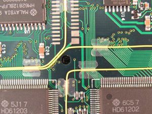
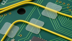
After the wire has been soldered at both ends and, if necessary, cleaned, it should be bonded to the board surface. Bond the jumper wire using one of the following methods.
A. Wire Dots or Tape Strips.
B. Quick Set Adhesive.
C. Hot Melt Adhesive.
D. Hot Bonding. Some jumper wires are manufactured with a special thermoset adhesive coating and are thermally bonded to the board surface with a special bonding tool.
Conclusion
Engineers can ensure secure, reliable connections in circuit board assemblies by following these 10 essential rules for jumper wires. Adhering to industry best practices will enhance the overall performance, longevity, and maintainability of electronic devices.
Several members of the Circuit Technology Center team contributed to this technical paper. Images may be altered or recreated to protect proprietary information.