Outline
This procedure outlines the process for reclaiming BGA (Ball Grid Array) and CSP (Chip Scale Package) components for reuse.
Minimum Skill Level - Expert
Recommended for technicians with advanced soldering and component rework skills and extensive experience in most repair/rework procedures.Conformance Level - High
This procedure most closely duplicates the physical characteristics of the original, and most probably complies with all the functional, environmental and serviceability factors.| Procedure References | |
| 1-0 | 1.0 Foreword |
| 10-1 | 10.1 Introduction To Component Reclaim |
| 2-1 | 2.1 Handling Electronic Assemblies |
| 2-2 | 2.2 Cleaning Procedures |
| 2-5 | 2.5 Baking and Preheating |
| 9-0 | 9.0 BGA Component Rework and Reballing Procedures |
Tools and Materials

Hot air or infrared BGA component rework system. |

General purpose cleaner for removing contamination. |

Batch or inline cleaning system for removing fluxes and contamination. |

Tool and nozzles to deliver precise flow of hot air. |

Temperature adjustable heated plate to pre-heat components and circuit boards prior to tinning and reflow. |

Precision microscope with stand and lighting for work and inspection. |

Protect your eyes and your vision with proper safety glasses. |

Used to prepare solder surfaces and to prevent formation of oxides during soldering. |

Manual or powered vacuum pickup tool for handling small parts and electrinic components. |

Nonabrasive, low-linting wipes for cleanup. |
Procedure
- Ensure the components meet the acceptable Moisture Sensitivity Level (MSL) for processing.
Note: For details on baking and moisture control, refer to Procedure 2.5 Baking and Preheating.. - Remove conformal coating from the component if present. See Section 2 for conformal coating removal guidelines.
- If needed, clean the rework area to remove contamination, oxides, or residues.
- Secure the circuit board in a board holder (See Figure 2) or on the base of the rework tool or system (See Figures 3 and 4). A hot plate may be used to provide added bottom-side heating.
- Install the appropriate size nozzle based on the component type. Set system controls to the required settings to minimize thermal stress and prevent overheating.
- Apply flux to the solder joints. (See Figure 5)
- Align the component under the nozzle. (See Figure 6)
- Lower the nozzle, check the alignment, and adjust as needed.
- If a vacuum lift is available, lower the vacuum pickup until it contacts the component.
- Initiate the hot gas reflow cycle, observing the solder melt on all solder ball joints. Then activate the system vacuum and raise the nozzle and component a minimum of 25mm above the circuit board. (See Figure 6)
- Turn off the heated air flow while maintaining the vacuum to retain the component.
- Allow the component to cool for at least 10 seconds before removal.
- Clean the component as required. Visually inspect for cleanliness and physical condition.
- This removal process will damage the solder balls on the component. The solder ball will require replacement before the component can be reused. See Section 9 BGA Component Rework and Reballing Procedures.
Evaluation
- Visual examination
- Tests or other inspection criteria as specified.
Images

Component Reclaim, BGA/CSP Components
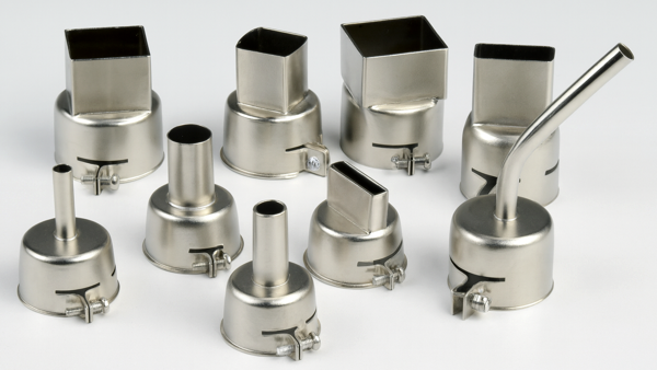
Select the proper nozzle based on the component size.
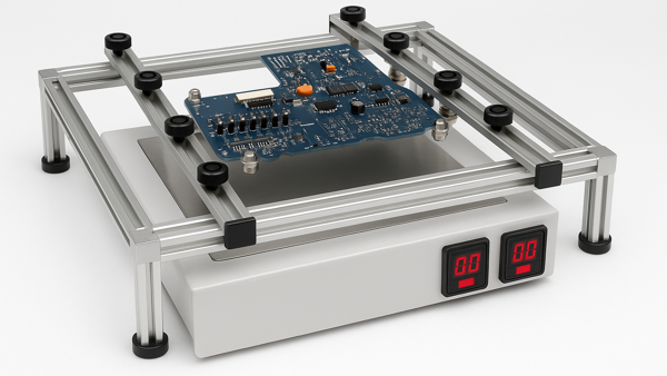
Secure the circuit board in a board holder or on the base of the rework system. A hot plate may be used to provide added bottom-side heating.
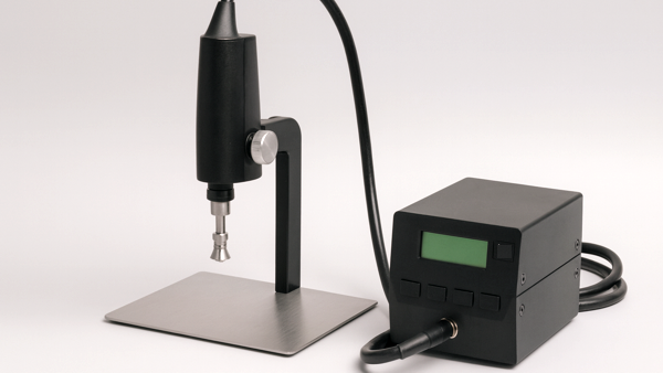
Typical hot-air rework tool.
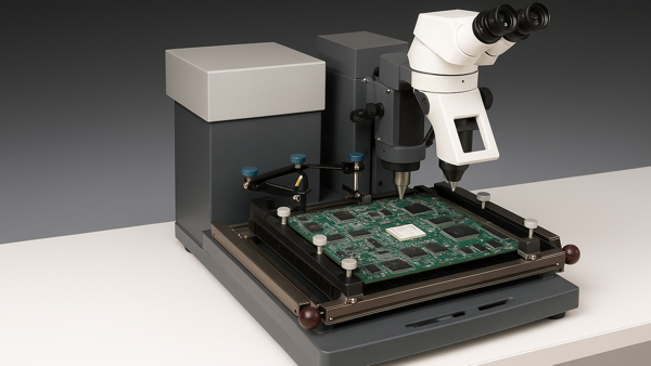
Typical hot-air rework system.
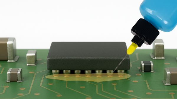
Apply flux to the solder joints.
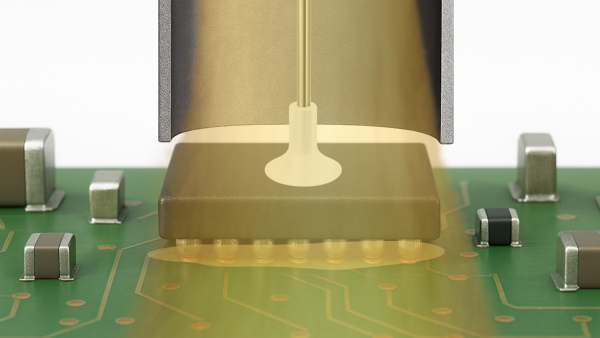
Direct hot air over the component until complete solder melt has been observed. Then lift the component off the board surface.