You have a new board, and the BGA component doesn't fit the board footprint. Is this a nightmare of a problem? We see it at Circuit Technology Center every other month or so.
It seems to be a problem OEMs face early in the development cycle. In this actual example, the flagship product an OEM was working on reached the post-assembly test phase when they discovered a hang-up.
The BGA that was loaded at several locations on the board was the wrong one! To further complicate matters, the footprint of the correct BGA was not the same as the original. You might ask, "How could this happen?".
Consider the mind-boggling variables. Marketing, engineering, and customers all push to fill a niche to get to market first. People change their minds; new components come along. Stuff happens!
In any event, there was a problem. You might ask, why not re-spin the board? In this case, the boards were already populated when this component mismatch was identified. The time and money involved in board re-spin and population, board fabrication time, component purchase time, and assembly time were prohibitive.
What could be done? Traditionally, jumper wires could be employed with through-hole and standard SMT parts. That is to connect all of the leads on the newly specified component to the places where they need to be on the board. Hardly an elegant-looking fix, but in some cases, it's all that's needed to get the job done.
However, we designed a daughter board to mate between the board footprint and the new BGA component in this case. Sounds simple enough, doesn't it? Like most fancy rework projects, it's a bit easier to think about than to implement.
All of the connections from the new component had to be interfaced with an existing footprint on the board surface. This required using an 8-layer daughter card. This added thickness may cause a height issue in some cases, but fortunately, not in this case. In addition, several capacitors and resistors were also required and added to the daughter card's perimeter.
So what are the concerns? Will stacking a new BGA component on top of this daughter card create reflow problems? Will the daughter card warp or sit too low, causing shorts or opens? Are multiple reflow cycles at this location likely to cause burning or layer separation? Serious concerns and all were carefully addressed.
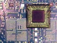
The following are the details of how we fixed this BGA footprint mismatch. The original BGA component was a 289-ball full array. The new BGA component was a 256-ball perimeter array. (See Figure 1)
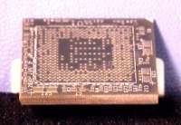
Due to the dense circuitry and electrical routing needed, the daughter card was eight layers and .100 inches thick. (See Figure 2)
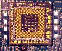
Fortunately, the thickness of this board did not present a height problem. However, from a rework standpoint, there was a concern about the heating of the layers during the several rework steps. We opted to use high-temperature balls for the bottom side of the daughter card. Even though eutectic balls would have supported the weight of the combined daughter card and new BGA, the high-temperature balls allowed for whatever minor bumps, jumps, and hiccups might occur. Since the daughter card was to be soldered before the new BGA component, using high-temperature balls would prevent tipping or shorting of the daughter card during the reflow of the new BGA component. (See Figure 3)
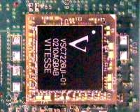
The placement would be done in this order so that the second reflow profile could be designed to heat the new BGA component from the top and minimize the heat that would be transmitted to the circuit board. (See figure 4). Once the final BGA placement was done, we hand-soldered the discrete components onto the daughter card.
In summary, the steps we followed were:
- Remove the original 289-pin BGA component.
- Clear the site of excess solder.
- Add solder paste to the BGA pattern on the original circuit board using a Flextac BGA Rework Stencil.
- Soldered the daughter card to the original circuit board using high-temperature solder balls.
- Add solder paste to the BGA pattern on the top of the daughter card using a Flextac BGA Rework Stencil.
- Solder the new eutectic-balled BGA component onto the daughter card.
- Hand solder the accompanying capacitors and resistors to the perimeter of the daughter card.
This type of modification has a solid track record. It's a bit of work but it is an elegant solution. Just in case you're wondering, after a modest setup fee, we charged $185.00 per board for a total of 22 assemblies.
Several members of the Circuit Technology Center team contributed to this feature story. Images may be altered or recreated to protect proprietary information.