Here's a situation that you may experience someday if you haven't already. A start-up electronics company discovered a problem. Their contract assembler had just delivered the first 100 boards. Despite a thorough design review and initial prototype, they found that each board needed rework at several ball grid array (BGA) sites.
The rework involved changing the circuit paths at the BGA sites, requiring not only adding new circuits but also severing the old ones.
The procedure for handling this problem is as follows: After removing the BGA components and cutting the connections from the subject BGA pads to the connection vias, the BGA pads were removed. New BGA pads were then thermally bonded to the board surface, and copper circuit tracks were connected to them. The circuit tracks were routed to the perimeter of the BGA sites. Wires were then attached to these new tracks.
This type of rework can be difficult because it requires demonstrated capabilities across multiple disciplines, in this case, three distinct skill sets. First, the expertise required for BGA removal and replacement. The second involves proficiency in milling and cutting operations. The third skill set involves adding new BGA pads, copper tracks, and jumper wires.
The Detailed Procedure Follows
- Remove the subject BGA components using standard BGA rework equipment. Typically, this would be a hot-air rework system. If the density of the assembly mandates the use of bottom-side heating or pre-heating, an area-source convective heater, hotplate, or bottom-side hot-air nozzle can be used, depending on the configuration and make of the equipment.
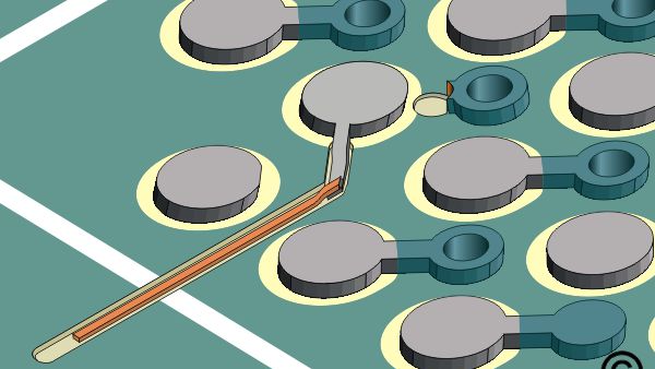
- Cut the short conductor (dog bone) connecting the BGA pad to the connecting via using a high-speed precision drill. Use a carbide end mill approximately 0.015" in diameter. Exercise care not to cut into the circuit board surface more than is necessary to sever the conductor. (See Figure 1).
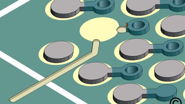
- Remove the subject BGA pad. The pad can be gently peeled off with a knife. Apply heat from a soldering iron if needed to reduce the adhesion to the board. (See Figure 1).
- Use a milling machine to make a shallow channel in the board surface from the BGA pad area to the perimeter of the BGA site. Tight spacing may restrict the width of the channel to 0.002" or less. Use a carbide end mill approximately 0.002 in wider than the new connecting circuit. (See Figure 1).
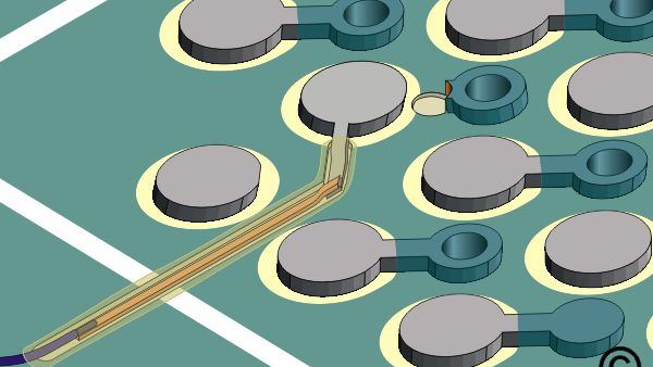
- Bond a replacement BGA pad in place using a bonding iron. The new BGA pad must have a tail to line up with the circuit track to be added next in this procedure. (See Figure 2).
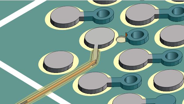
- Lap solder a copper circuit track to the tail extending from the BGA pad. Run this new track along the milled path out beyond the perimeter of the BGA site. (See Figure 2).
- Solder one end of a fine-gauge wire to the extending circuit. The opposite end of the wire will be soldered later. (See Figure 3).
- Clean the area and overcoat the new circuit and solder joints with a thin layer of high-strength, high-temperature epoxy.
- Test the new circuit and replace the BGA component.
- Solder the remaining end of the wire to complete the new circuit. Complete the final inspection using X-ray inspection equipment.
Adding engineering change orders (ECOs) to BGA sites need not be a nightmare, although it is certainly a challenging rework procedure. It can be done reliably and safely by following the procedure outlined above.
The result will be a robust, reliable connection that can be depended upon until the appropriate design changes on the board are implemented to correct the situation. When performed correctly, it is a reliable fix that will save time, money, and countless otherwise perfect assemblies from the recycling bin.
Several members of the Circuit Technology Center team contributed to this feature story. Images may be altered or recreated to protect proprietary information.