Outline
This procedure outlines the process for reclaiming radial lead components for reuse.
Minimum Skill Level - Advanced
Recommended for technicians with soldering and component rework skills and exposure to most repair/rework procedures, but lacking extensive experience.Conformance Level - High
This procedure most closely duplicates the physical characteristics of the original, and most probably complies with all the functional, environmental and serviceability factors.| Procedure References | |
| 1-0 | 1.0 Foreword |
| 10-1 | 10.1 Introduction To Component Reclaim |
| 2-1 | 2.1 Handling Electronic Assemblies |
| 2-2 | 2.2 Cleaning Procedures |
| 2-5 | 2.5 Baking and Preheating |
Tools and Materials

General purpose cleaner for removing contamination. |

Batch or inline cleaning system for removing fluxes and contamination. |

Manual or powered desoldering tool or system. |

Precision microscope with stand and lighting for work and inspection. |

General purpose oven for drying, baking and curing epoxies. |

Protect your eyes and your vision with proper safety glasses. |

Used to prepare solder surfaces and to prevent formation of oxides during soldering. |

Solder fountain system for selective component removal and replacement. |

Multiple sizes and tip configurations of tweezers for various small parts handling needs. |

Nonabrasive, low-linting wipes for cleanup. |
Procedure
Manual Vacuum Desolder Method
- Ensure the components meet the acceptable Moisture Sensitivity Level (MSL) for processing.
Note: For details on baking and moisture control, refer to Procedure 2.5 Baking and Preheating.. - Remove conformal coating from the component leads if present. See Section 2 for conformal coating removal guidelines.
- If needed, clean the rework area to remove contamination, oxides, or residues.
- If needed, secure the circuit board in a board holder. (See Figure 1)
- Install the appropriate size tip in the vacuum desolder tool. Set the temperature to the required settings to minimize thermal stress and prevent overheating. (See Figure 2)
- Inspect the size of the solder joints on the component to be removed. If the size of the solder joint fillets is minimal, it may be desirable to add additional solder to form an "excess solder" joint. This will improve the thermal linkage.
- Apply flux to the solder joints. (See Figure 3)
- Align the desolder tip with a component lead end and lightly make contact with the solder joint. Keep the desolder tip off the pad by allowing it to slide around on a film of solder. (See Figure 4)
Caution: Do not apply pressure with the desolder tool tip to the lands or other conductive patterns. - After the solder has melted, start a rotating or oscillating motion with the desolder tip. Continue the rotating motion until a change in the "feel" of the rotating motion occurs. At this instant, the solder in the solder joint is completely molten. Immediately activate the vacuum, extracting the solder from the solder joint.
- Maintain rotation of the desolder tip while the continuous vacuum is being applied. This allows air to cool both the component lead and the plated-through hole, preventing the component lead from resoldering to the side of the plated-through hole.
- After the solder has been extracted from the solder joint, remove the desolder tip from the component lead while maintaining a continuous vacuum.
- Maintain a continuous vacuum for a few seconds to clear the desolder tip.
- Turn off the vacuum.
- Desolder each of the remaining components leads individually using a skipping method to reduce thermal buildup at adjacent hole locations.
- Probe each component lead to be sure that they are not soldered to the side of the plated hole, and then remove the component.
Note: If each lead is not entirely free, resolder the joint and repeat the process. - Clean the area.
Solder Fointain Method
- Ensure the components meet the acceptable Moisture Sensitivity Level (MSL) for processing.
Note: For details on baking and moisture control, refer to Procedure 2.5 Baking and Preheating.. - Remove conformal coating from the component leads if present. See Section 2 for conformal coating removal guidelines.
- If needed, clean the rework area to remove contamination, oxides, or residues.
- Turn on the solder fountain system and allow the solder to reach the proper operating temperature. Clean the machine as needed, and test run the pump to be sure there is no buildup of contamination that may cause a drag on the pumping system. (See Figure 6)
- Select the proper nozzle and install it into the solder fountain system. A nozzle that is too large will expose the circuit board surface to unnecessary heat. A nozzle that is too small may not reflow all the component leads.
- Check the table height and solder wave height to be sure they are properly set for the circuit board. (See Figure 7)
- Apply flux to all the leads of the component to be removed. Apply the flux to both the top and bottom side solder fillets.
- Place the circuit board over the nozzle. Check the position using the alignment light.
- Activate the solder fountain. Once full solder reflow has been achieved, extract the component with the extractor tool. Operator skill and experience are required to prevent damage caused by premature removal or heat damage due to delayed removal.
- Immediately drop the solder fountain.
- Allow the component to cool before handling and inspection.
- Clean the area and inspect for signs of damage.
Evaluation
- Visual examination
- Tests or other inspection criteria as specified.
Images

Component Reclaim, Radial Lead Components Components
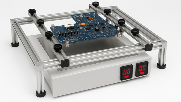
If needed, secure the circuit board in a board holder.

Typical vacuum desolder system.

Apply flux to the solder joints.
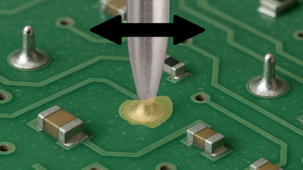
Align the desolder tip with a component lead. Start a rotating or oscillating motion with the desolder tip.

Desoldered joint with the lead detached from the plated hole.

Solder fountain system.

Solder fountain system solder wave.