Outline
This procedure outlines the process for reclaiming chip components for reuse.
Preparation
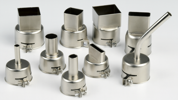
This method uses hot air or gas nozzles that do not contact the component directly. Heated gas or air is forced through a specially designed nozzle and directed onto the component terminations and surface pads. Nozzles are available in several sizes to suit component packages. (See Figure 1) Select the proper nozzle based on the component size. Verify the nozzle fit before processing. Some nozzle designs target only the leads and pad areas, while others heat the entire component body. Specific nozzles may include vacuum assist to lift the component from the board surface after solder reflow.
Minimum Skill Level - Advanced
Recommended for technicians with soldering and component rework skills and exposure to most repair/rework procedures, but lacking extensive experience.Conformance Level - High
This procedure most closely duplicates the physical characteristics of the original, and most probably complies with all the functional, environmental and serviceability factors.| Procedure References | |
| 1-0 | 1.0 Foreword |
| 10-1 | 10.1 Introduction To Component Reclaim |
| 2-1 | 2.1 Handling Electronic Assemblies |
| 2-2 | 2.2 Cleaning Procedures |
| 2-5 | 2.5 Baking and Preheating |
Tools and Materials
General purpose cleaner for removing contamination. |
Tool and nozzles to deliver precise flow of hot air. |
Temperature adjustable heated plate to pre-heat components and circuit boards prior to tinning and reflow. |
Precision microscope with stand and lighting for work and inspection. |
Protect your eyes and your vision with proper safety glasses. |
Used to prepare solder surfaces and to prevent formation of oxides during soldering. |
Multiple sizes and tip configurations of tweezers for various small parts handling needs. |
Manual or powered vacuum pickup tool for handling small parts and electrinic components. |
Nonabrasive, low-linting wipes for cleanup. |
Procedure
- Ensure the components meet the acceptable Moisture Sensitivity Level (MSL) for processing.
Note: For details on baking and moisture control, refer to Procedure 2.5 Baking and Preheating.. - Remove conformal coating from the component if present. See Section 2 for conformal coating removal guidelines.
- If needed, clean the rework area to remove contamination, oxides, or residues.
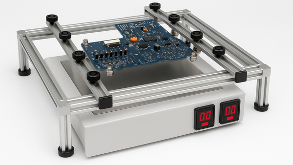
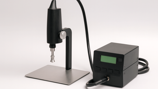
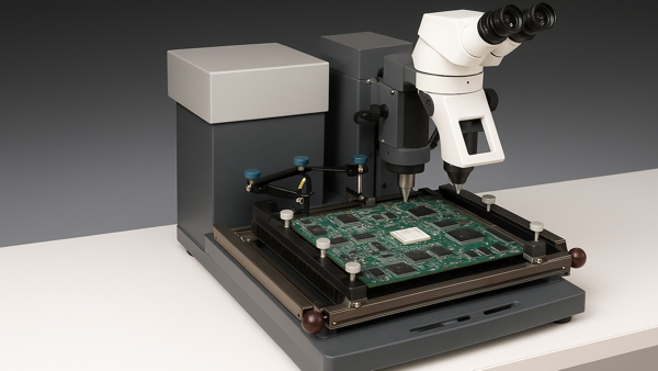
- Secure the circuit board in a board holder (See Figure 2) or on the base of the rework tool or system (See Figures 3 and 4). A hot plate may be used to provide added bottom-side heating.
- Install the appropriate size nozzle based on the component type. Set system controls to the required settings to minimize thermal stress and prevent overheating.
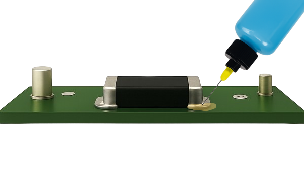
- Apply flux to component leads. (See Figure 5)
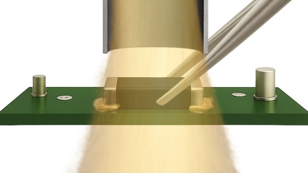
- Align the component under the nozzle. (See Figure 6)
- Lower the nozzle, check the alignment, and adjust as needed.
- If a vacuum lift is available, lower the vacuum pickup until it contacts the component.
- Initiate the hot gas reflow cycle, observing the solder melt on all leads. Then activate the system vacuum and raise the nozzle and component a minimum of 25mm above the circuit board.
- If the vacuum lift is not used, lift the component of the circuit board using tweezers or a gripper tool. (See Figure 6)
- Turn off the heated air flow.
- Allow the component to cool.
- Clean the component as required. Visually inspect for cleanliness and physical condition.
- If the component is to be resoldered manually, lead restoration may not be required. If the component will be processed using automatic placement equipment, or if the specification requires specified lead finish conditions, refer to Section 11.
Evaluation
- Visual examination
- Tests or other inspection criteria as specified.
Images
Component Reclaim, Chip/Discrete Components
Select the proper nozzle based on the component size.
Secure the circuit board in a board holder or on the base of the rework system. A hot plate may be used to provide added bottom-side heating.
Typical hot-air rework tool.
Typical hot-air rework system.
Apply flux to the component terminations.
Direct hot air over the component until the solder melts. Then lift the component off the citcuit board surface using tweezers.