We've all heard of via in pad, blind vias, and even buried vias, but have you ever experienced the "via to nowhere" phenomenon? Well, here's how it goes.
We received a distress call from a customer who found they were missing ten vias on their now-populated circuit boards. The vias were supposed to connect from surface circuitry to an internal ground layer. Every other part of the design was intact, except for the missing plated via connections.
What is the best approach when trying to create a through-board connection? Using a solder-plated copper eyelet swagged into the circuit board is a common repair technique. However, the hole size or board thickness can sometimes limit the use of an eyelet. What then?
Well, there is a relatively obscure procedure listed in our guidebook: 4.2.5 Conductor Repair, Through Board Wire Method. This procedure includes using a wire to connect through the board. In this case, the wire method was the perfect solution to correct the missing vias.
The board's design had the isolation holes drilled to .018"; therefore, the area for the wire to fit through the board was tight. The design also called for several of the holes to connect to the surface and to an internal plane.
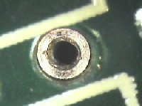
The repair process consisted of drilling a .010" hole to allow for the installation of a non-insulated 30-gauge wire through the board.
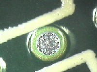
The clearance holes were drilled through the center of the via's surface pad.
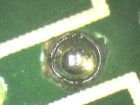
The opposite side of the location was precisely machined to expose the surface of the inner plane to which the wire was to connect. This is a difficult step done on a precision drill system with the aid of a microscope.
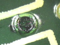
After both surfaces were exposed, the wire was inserted through the drilled hole and bent over to overlap the two exposed pads. The two points were then soldered to establish the desired connections.
The final touch-up of the area included sealing the perimeter with epoxy to secure the wire. Many times, we have referenced odd IPC procedures and wondered why they were ever included in printing the IPC Repair/Rework guidebook. As obscure as this procedure was, it was the best solution to recover these circuit boards.
Several members of the Circuit Technology Center team contributed to this feature story. Images may be altered or recreated to protect proprietary information.