Circuit Technology Center 22 Parkridge Road
Haverhill, MA 01835 USA
www.circuitrework.com

5.2 Plated Hole Repair, Double Wall Method

Procedure to repair damaged plated holes that have an inner inner layer connection on circuit board assemblies.

Minimum Skill Level: Advanced
Conformance Level: Medium


REQUEST FOR QUOTE    GUIDES INDEX
slide 1
Plated Hole Repair, Double Wall Method
slide 2
Insert the eyelet into the hole.
slide 3
Completed repair.
plating-system
Eyelets are the most common way to repair plated holes conformint to IPC guidelines. LEARN MORE
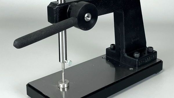
eyelet press
This rugged, heavy-duty press precisely forms eyelets for repair or assembly, ensuring the eyelets meet industry guidelines. LEARN MORE
generic
We're here to help restore damaged circuitry and plated holes following IPC guidelines. LEARN MORE
SLIDESHOW STARTING
Outline

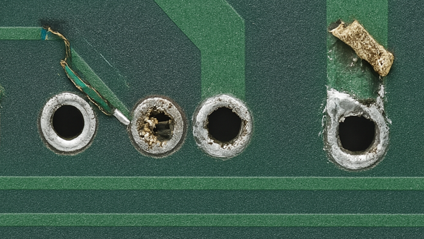
This procedure covers the use of an eyelet for the repair of a damaged land on a plated hole that has an inner layer connection.

Caution: This method is used to restore the integrity of a through connection on a multilayer circuit board, having an inner layer connect, but ONLY if the full barrel of the plated through hole remains intact. If there is barrel damage, see the appropriate procedure.

Caution: This method will reduce the inside diameter of the hole. The minimum hole size requirement must be checked for acceptance.

Minimum Skill Level - Advanced
Recommended for technicians with soldering and component rework skills and exposure to most repair/rework procedures, but lacking extensive experience.

Conformance Level - Medium
This procedure may have some variance with the physical character of the original and most likely varies with some of the functional, environmental and serviceability factors.

Acceptability References
IPC-A-600 2.0 Externally Observable Characteristics
IPC-A-600 3.0 Internally Observable Characteristics
Procedure References
1.0 Foreword
2.1 Handling Electronic Assemblies
2.2 Cleaning
IPC7721 5.2 Plated Hole Repair, Double Wall Method
Tools, Materials and Supplies

Procedure

Eyelet Selection Criteria

ID - Inside Diameter
The eyelet inside diameter should be .075 - .500 mm (.003"-.020") greater than the component lead diameter.

OD - Outside Diameter
The clearance hole drilled through the circuit board should allow the eyelet to be inserted without force, but should not exceed .125 mm (.005") greater than the eyelet's outside diameter.

LUF - Length Under Flange
The length of the eyelet barrel under the flange should be .630 - .890 mm (.025" - 035"), greater than the thickness of the circuit board. This added length allows for proper protrusion when setting the eyelet.

FD - Flange Diameter
The eyelet flange diameter should be small enough to prevent interference with adjacent lands or circuits.

Note: Be sure to select an eyelet meeting the proper criteria. An eyelet with an oversized flange may interfere with adjacent circuits. An eyelet that is too short will not protrude through the circuit board for proper setting.

Procedure

  1. Clean the area.
  2. Examine the hole to ensure that there is no damage to the wall of the hole. Check continuity to establish the integrity of the connection.
  3. Select an eyelet using the Eyelet Selection Criteria. Use a pin gauge and caliper to measure the existing plated hole dimensions. The eyelet must have an inside diameter sufficient to receive the component lead and an outside diameter that will allow the eyelet to be inserted into the hole without force.
  4. Remove oxides from the surface lands where the eyelet will be installed using a buffer and clean.
  5. Apply a small amount of liquid flux to the land or circuit on the circuit board surface, if any, and tin with solder using a soldering Iron and solder. Clean the area.
  6. Insert the eyelet into the hole. If a new circuit is required, it may extend into the hole, and the eyelet flange will secure it in place. (See Figure 1)
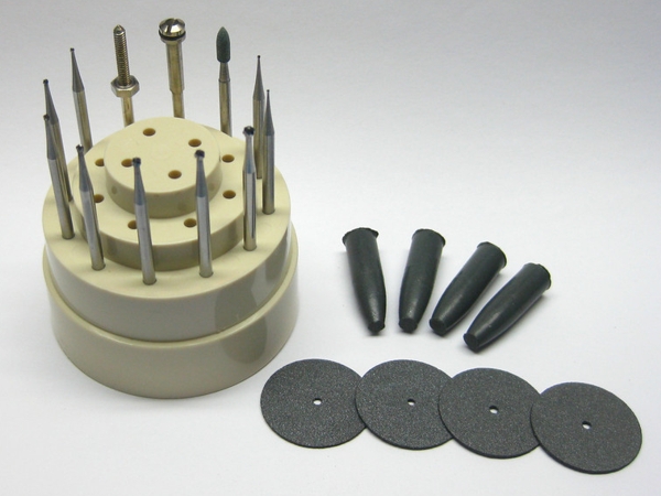
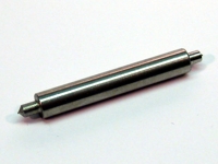
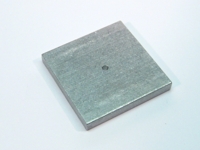
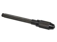
  7. Select the proper setting tools and insert them into the Eyelet Press or Tool Grip. (See Figure 2)
  8. Turn the circuit board over and rest the eyelet flange on the lower setting tool. 
  9. Apply firm, even pressure to flare the eyelet barrel. 
  10. Change the upper setting tool from a flare tool to a flat-end tool. Apply firm, even pressure to flatten the eyelet barrel. 
    Note: Inspect the eyelet for evidence of damage. Refer to IPC-A-610 Acceptability of Electronic Assemblies.
  11. Apply a small amount of liquid flux and solder the eyelet flanges to the lands on the circuit board surface if necessary. Clean the area. Inspect for good solder flow and wetting around the eyelet flanges and lands. 
  12. Clean the area.
  13. Install the component lead and solder, if required.

Evaluation

  1. Visual examination, the dimensional requirement of land diameter and inside diameter.
  2. Electrical continuity measurement.
Images and Figures
Plated Hole Repair, Double Wall Method
Insert the eyelet into the hole.
Figure 1. Insert the eyelet into the hole.
Completed repair.
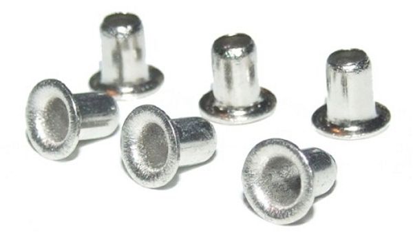
Figure 2. Completed repair.
Contact Us/Quote Request


Send Documents *
No file chosen
No file chosen
No file chosen
No file chosen
No file chosen

Notes/Questions/Requests

Product Type
Assemblies Bare PCBs Other

Quantity

Delivery Schedule Request
3 Weeks 2 Weeks 1 Week
2-3 Days 1 Day

Security Check


* You may upload PDFs and other file types (max 4 MB each). For multiple files, zip them or send to info@circuitrework.com

Form Security
Our forms run on AWS with an industry-leading firewall. Data is encrypted at rest with AES-256 and in transit using TLS 1.2+.