Outline
This procedure covers repairing a damaged hole with no inner layer connection. An eyelet is used to repair the damage to the hole, and the eyelet flange replaces the lands on the circuit board surface.
Caution: This procedure is used only to restore the integrity of a through connection in a double-sided board or a multilayer board where there is no inner layer connection. If there is an inner layer connection, see the appropriate procedure.
Minimum Skill Level - Intermediate
Recommended for technicians with skills in basic soldering and component rework, but may be inexperienced in general repair/rework procedures.Conformance Level - High
This procedure most closely duplicates the physical characteristics of the original, and most probably complies with all the functional, environmental and serviceability factors.| Procedure References | |
| 1-0 | 1.0 Foreword |
| 2-1 | 2.1 Handling Electronic Assemblies |
| 2-2 | 2.2 Cleaning Procedures |
Tools and Materials

Ball mills, abrasives and cutting tools for working on circuit boards. |

General purpose cleaner for removing contamination. |

Disposable brushes for solvent cleaning and application of coatings. |

Heavy duty eyelet press designed to set and form eyelets in circuit boards. |

Copper and brass eyelets electroplated with tin designed for repair of plated through holes. |

Sturdy rack for PCBs used for rework and positioning. |

Precision microscope with stand and lighting for work and inspection. |

Use to provide accurate measurements for thickness and hole diameters. |

Nine precision-crafted tools for detailed circuit board work. |

Training kit to practice circuit board repair skills prior to testing for certification. |

Used to properly form eyelets used to repair plated holes in circuit boards. |

Properly maintained soldering iron and properly sized soldering iron tips. |

Support base for Setting Tool when forming eyelets for plated hole repair. |

Handy tool has vise jaws to grip small items. |

Nonabrasive, low-linting wipes for cleanup. |
Procedure
Eyelet Selection Criteria
ID - Inside Diameter
The eyelet inside diameter should be .075 - .500 mm (.003"-.020") greater than the component lead diameter.
OD - Outside Diameter
The clearance hole drilled through the circuit board should allow the eyelet to be inserted without force but should not exceed .125 mm (.005") greater than the eyelet's outside diameter.
LUF - Length Under Flange
The length of the eyelet barrel under the flange should be .630 - .890 mm (.025" - 035"), greater than the thickness of the circuit board. This added length allows for proper protrusion when setting the eyelet.
FD - Flange Diameter
The eyelet flange diameter should be small enough to prevent interference with adjacent lands or circuits.
Note
Be sure to select an eyelet meeting the proper criteria. An eyelet with an oversize flange may interfere with adjacent circuits. An eyelet that is too short will not protrude through the circuit board for proper setting.
Procedure
- Clean the area.
- Select an eyelet using the Eyelet Selection Criteria. Use a pin gauge and caliper to measure the existing plated hole dimensions.
- Insert the appropriate ball mill into the Micro-Drill System or Tool Grip. Drill out the hole, removing all the plating. The drilled hole should be .025 - .125 mm (.001" - .005") larger than the eyelet O.D.
Caution: This procedure may isolate internal connections on multilayer circuit boards. - Clean the area.
- Apply a small amount of liquid flux to the land or circuit on the circuit board surface, if any, and tin with solder using a soldering iron and solder. Clean the area.
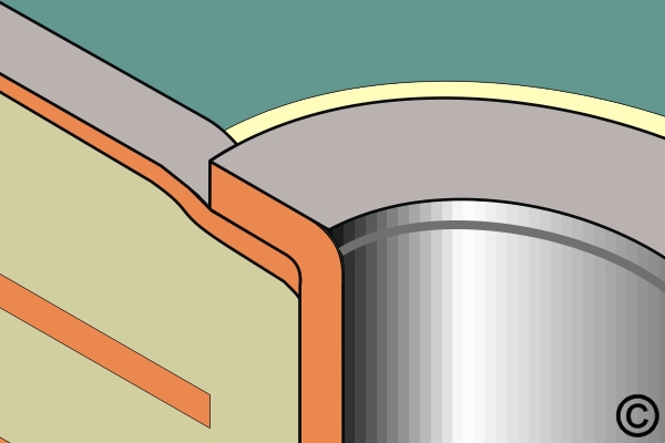
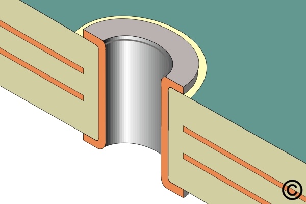
- Insert the eyelet into the hole. If a new circuit is required, it may extend into the drilled hole, and the eyelet flange will secure the new circuit in place. (See Figure 1)
- Select the proper setting tools and insert them into the Eyelet Press System or Tool Grip and Tool Base.
- Turn the circuit board over and rest the eyelet flange on the lower setting tool.
- Apply firm, even pressure to flare the eyelet barrel.
- Change the upper setting tool from a flare tool to a flat-end tool. Apply firm, even pressure to flatten the eyelet barrel.
Note: Inspect the eyelet for evidence of damage. Refer to IPC-A-610 Acceptability of Electronic Assemblies. - Apply a small amount of liquid flux and solder the eyelet flanges to the lands on the circuit board surface if necessary. Clean the area. Inspect for good solder flow and wetting around the eyelet flanges and lands.
Evaluation
- Visual examination of the dimensional requirements of the land diameter and the inside diameter.
- Electrical continuity measurement.
Images