Outline
The guides in this section cover the requirements for tinning components using robotic hot-solder dip systems to replace finishes on various electronic components. The objective is to ensure that robotic hot-solder dipping does not increase the failure rate of electronic components after solder dipping and that a quality process is performed each time.
| Procedure References | |
| 1-0 | 1.0 Foreword |
| 2-1 | 2.1 Handling Electronic Assemblies |
| 2-2 | 2.2 Cleaning Procedures |
Procedure
1. Reasons for Solder Dip
There are three primary reasons to solder dip electronic components: leads, pads, and terminations.
- Tin Whisker Mitigation
Solder tinning for tin-whisker mitigation differs from solder dip for solderability. For tin whisker mitigation, the termination must be coated over its entire length up to the package surface. During solder dip, the piece part experiences temperature differences that are greater than those encountered during typical board-level assembly. In addition, fluxes used during the dipping process can become trapped in minor delaminations, such as those commonly found in plastic piece parts, leading to reliability issues. The solder dip process must be qualified and carefully controlled to avoid these concerns. Typically, tin whisker mitigation replaces a pure tin finish with a solder alloy containing various percentages of lead. Replacement finishes using lead-free alloys should be evaluated for tin whisker mitigation before implementation. - Finish Restoration
Solder tinning for lead, pads, and terminations is required when the solder finish does not meet requirements due to long-term storage or environmental exposure. - Reclamation and Salvage
Solder tinning for lead, pad, and termination after component reclamation is designed to meet requirements so components can be reused, including through automated assembly equipment. In addition, during component reclamation and salvage, leads, pads, and terminations may become distorted and misaligned. Realignment to meet specifications may be required.
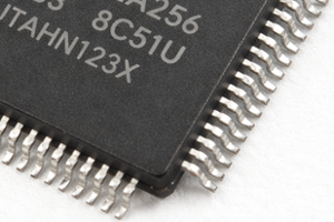
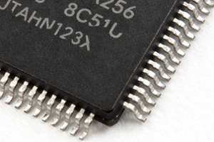
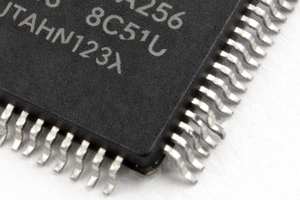
2. Robotoc Hot Solder Dip
Due to the need to fully control the immersion and emersion rates of component terminations and the dwell times in and between each process step, robotic hot-solder dip is recommended for electronic component tinning. Semi-automatic or purely manual solder-dipping processes may not fully control the immersion and emersion rates of component terminations and can only provide approximate dwell times in the solder bath. Greater variation in the process may increase the risk of damage, including latent reliability issues.
Manual dipping for full-finish replacement differs from current practice to meet solderability requirements due to the greater need for 100% coverage of the component body to prevent whisker growth. Certain electronic component package styles may not lend themselves to robotic hot solder dipping and may require alternative processing.
Note: For detailed information, refer to GEIA-STD-0006 Requirements for Using Robotic Hot Solder Dip to Replace the Finish on Electronic Piece Parts.
- GEIA-STD-0006
This standard defines the requirements for fully replacing undesirable surface finishes using robotic hot solder dip. Requirements for qualifying and testing the refinished components are also included. This standard covers replacing pure tin and Pb-free tin alloy finishes with SnPb finishes for subsequent assembly with SnPb solder. This standard covers process and testing requirements for a robotic dipping process and does not cover semi-automatic or purely manual dipping processes. - GEIA-STD-0006
This standard does not apply to manufacturers who initially build components with a hot-solder-dip finish. It applies to refinishing performed by a robotic hot-solder dip service supplier or by production facilities at the customer's site when the dipping is intended to achieve full coverage and replace Pb-free tin. Replacement of BGA spheres or CGA columns is not included in the scope of this standard. IEC TS 62647-4 may be used to replace BGA spheres. - GEIA-STD-0006
This standard requires suppliers and customers to incorporate these requirements into their operations to provide a consistent, well-controlled process for product applications that require significant control. Complete conversion of termination finishes from pure tin or Pb-free solder to SnPb will allow the use of electronic components for any of the Control Levels of GEIA-STD-0005-2 without mitigations. In addition to eliminating tin whisker risks, electronic components processed to this standard will exhibit enhanced solderability and joint reliability compared to most COTS finishes.
3. Requirements for Robotic Hot Solder Dipping Apparatus
Robotic Hot Solder Dipping Apparatus shall include the following.
- Feature a vacuum or mechanical pickup mechanism
- Do not damage the piece part or its terminations
- Do not utilize metal surfaces that may scratch or cause solder smears
- Be capable of controlling the dwell time in the pre-heat and solder pot within ±0.1 seconds
- Be capable of controlling the exit speed out of the solder pot to within ±0.12 inch (0.3 cm)/s
- Be capable of controlling the depth of immersion to within ±0.004 inch (0.01 cm)
- Ensure dipping of the full termination or other tin or Pb-free tin finished surface into the solder pot, including the side of the package (if applicable)
4. Apparatus for Gull-Wing Formed Leads
In addition to those requirements above, the dipping apparatus used for robotic hot solder dipping gull-wing formed leads shall also be capable of edge dipping the piece parts with the following controls:
- Solder dip immersion angle and direction of travel
- Solder dip withdrawal angle and direction of travel
- Ability to rotate the piece part to allow each side to be solder dipped independently
5. Apparatus for J-Leaded Formed Leads
In addition to the requirements above, the dipping apparatus used for robotic hot-solder dipping J-lead-formed leads shall be capable of edge- and planar-dipping the piece parts to cover neighboring termination surfaces not obstructed by the package body.
6. Overall Process Flow
Qualification of Process
- Before production, the refinishing process shall be qualified in accordance with GEIA-STD-0006.
- Dry Bake
The MSL of the piece parts shall be obtained/verified/by the customer. All parts with MSL 2 or greater shall be dry-baked before refinishing, in accordance with J-STD-033. Dry bake is not required for electronic components received in labeled dry bags with desiccant and humidity indicators reading less than 5% RH, or for Type 1 electronic components. Once the packaging has been opened, it shall be handled in accordance with J-STD-033. Moisture-sensitive electronic components received in unknown conditions shall be dry-baked per J-STD-033. The cumulative bake time limits of J-STD-033 shall not apply to baking before refinishing. - Fluxing
The flux used shall be per GEIA-STD-0006 or customer requirements, and shall be applied consistently and repeatedly to the piece parts. - Preheat
Components shall be preheated before robotic hot solder dipping. Preheat ramp-up rates shall not exceed the original piece part manufacturer's specifications, J-STD-020, J-STD-075, or as specified in engineering documentation. - Application of Solder
After flux and preheat, the part terminations shall be immersed in molten solder using a robotic hot-solder-dipping apparatus. The total time in solder shall not exceed 5 seconds per immersion. A dynamic wave or another method shall be used to remove solder dross. - Cool Down, Cleaning, and Drying Methods
Cooling rates shall not exceed the component manufacturer’s specifications, J-STD-020, J-STD-075, or as specified on engineering documentation. Cleaning shall be performed within 1 hour of solder dipping, following the flux manufacturer's recommendations or J-STD-033 and J-STD-075, where applicable. Drying shall be accomplished to prevent the redeposition of ionic material onto electronic components or to reduce the solderability of the components. - Rework
Piece parts within the production lot shall not be reworked more than twice. A single rework process is defined as one complete throughput through the robotic hot-solder-dipping process for any combination of package side(s) after the initial robotic hot-solder dip. Any damaged piece parts shall be segregated, marked as defective, and returned to the customer; this includes piece parts dropped into the solder pot or on the floor, or those exhibiting physical damage after a fall. - Inspection and Testing
Electronic components shall be tested in accordance with the applicable test methods defined in GEIA-STD-0006 or as defined by customer drawings. If any failures occur during the applicable test methods during production lot testing, the customer shall be notified. Failed tested electronic components shall be segregated, marked as defective, and returned to the customer. Production electronic components from failed lots shall be identified and returned unless the sample devices are screened for defects. - Post-Process Baking
After all processing and inspection, electronic components that were dry baked shall be dry baked again in accordance with J-STD-033 and then dry packaged in moisture barrier bags. The cumulative bake time shall be reset to "zero" upon final packaging.
7. Straightening Component Leads
Straightening and realigning leads on QFP, gull-wing, J-lead, and other leaded surface-mount or through-hole components that are bent, twisted, or otherwise misaligned may require adjustment before reuse, whether by manual soldering or automated machine placement. A variety of tools may be required, including fine-tip smooth jaw pliers, lead-forming tweezers, and component lead alignment template/fixtures.
Before adjustment, perform a visual inspection to identify all leads for bends, twists, or displacement from the normal seating plane. The lead straightening procedure should reposition any misshapen leads without stressing the leads. Using smooth-jaw pliers or lead-forming tweezers, lightly bend the misaligned lead back to its original position in small, controlled increments. Avoid large deflections that can fatigue the metal. If a lead is twisted, rotate gently at the tip while supporting near the heel to prevent stress on the package body. After each adjustment, check lead coplanarity and pitch against a lead alignment gauge. Ensure all leads rest on the same seating plane within IPC-610 tolerance (typically =0.10 mm gap). Verify that lead spacing matches the component specification. If required, clean with approved solvent and a lint-free wipe to remove oils from handling. Allow to dry before further processing.
8. Conformance Levels
Each procedure lists a Level of Conformance that the product shall attain upon successful completion. The Level of Conformance ratings follow.
| Level | Component Body and Lead Condition | Example |
| High | Components meeting a High Conformance level have no imperfections in the component body or markings. The component leads, pins, or terminations comply with the manufacturer's specifications for plating finish, alignment, size, and shape. After removal from the original assembly, these components may require refinishing of the components, lead, pins, and terminations using robotic hot-solder-dip equipment to precisely control the component's immersion time and angle in the molten solder, thereby more closely matching the component manufacturer's specifications. Components with High conformance are suitable for automated assembly equipment processing. |
 |
| Medium | Components meeting a Medium Conformance level have no imperfections in the component body, but may have damaged or missing markings or part number designations. The component leads, pins, or terminations comply with the manufacturer's specifications for plating finish, alignment, size, and shape. After removal from the original assembly, these components may require refinishing of the components, lead, pins, and terminations using robotic hot-solder-dip equipment to precisely control the component's immersion time and angle in the molten solder, thereby more closely matching the component manufacturer's specifications. Components with High conformance are suitable for automated assembly equipment processing. |
 |
| Low | Components meeting a Low Conformance level may have scratches, discoloration, and other minor imperfections that do not degrade their performance, and may have damaged or missing markings or part number designations. The solder or plating finish on the component leads, pins, or terminations may not comply with the manufacturer’s specifications, but may be acceptable for manual soldering. Component leads, pins, or terminations may have slight misalignment, requiring straightening before installation or soldering. Components with Low conformance are not suitable for automated assembly equipment processing. |
 |
Images
