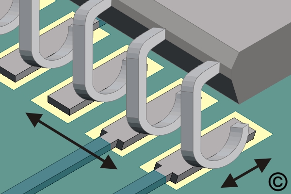
7.4.1 Soldering Surface Mount J Lead Components Point To Point Method |
|
Printed Board Type: R/F/C
Skill Level: Intermediate
Conformance Level: High
Revision: D
Revision Date: Jul 7, 2000
OUTLINE
 |
| Surface Mount J Lead Component |
|
This procedure covers the general guidelines for soldering surface mount J lead components. There is basically only one style of J lead component. Whether leads are on two sides or four sides, or whether the component is large or small, the soldering principles are the same.
 |
| Figure 1: Place component and check alignment. |
|
TOOLS & MATERIALSCleaner
Flux
Microscope
Solder
Soldering Iron with Tips
Wipes
PROCEDURE Preview a Video Clip (Size - 500KB)
- Add liquid flux to the corner pads.
- Place the component in position and hold it steady. The leads must be aligned with the pads. On large components this is best done by aligning the leads on opposite corners. (See Figure 1).
 |
| Figure 2: Place the soldering iron tip at the junction between the pad and component lead. |
|
Place the soldering iron tip at the junction between the pad and component lead at one of the corners. Apply additional solder as needed. (See Figure 2).
- Remove the tip. Wait a moment for the solder to solidify before soldering the opposite corner.
- After the opposite corner is soldered, solder the remaining leads.
- Clean, if required and inspect.
 |
| Figure 3:A - Dot indicates pin 1.B - Indicates pin 5.C - Indicates direction of pin count. |
|