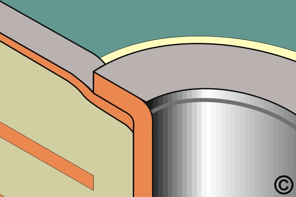
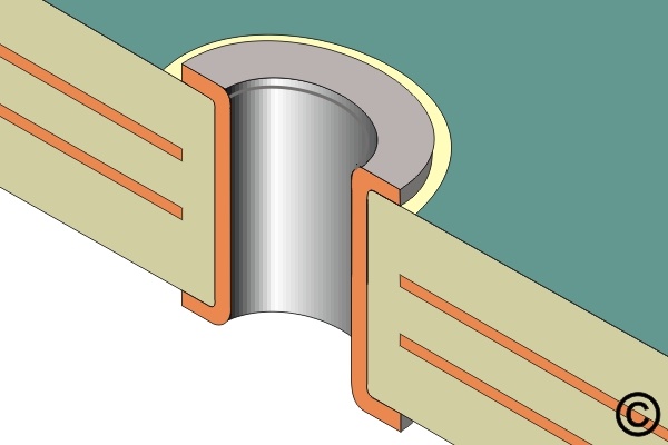
5.1 Plated Hole Repair, No Inner Layer Connection
Repair damaged plated through-holes with no inner layer connection using an eyelet. Learn drilling, preparation and eyelet forming methods to restore mechanical strength and solderability.
REQUEST FOR QUOTE GUIDES INDEX