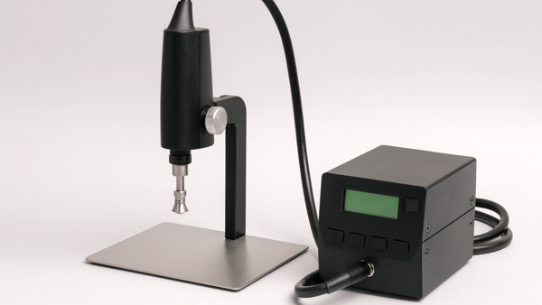
There are many hot air-based component rework tools and machines available today. Many are large, some small, but all have various means of delivering hot air to the component with varying degrees of process control. While there are a few high-end, fully automatic systems, most are semi-automatic or manual. This article will focus on simple bench-top style manual tools. (See Figure 1)
For most applications, large, complex machines used to remove gull wing, J-lead, and chip components are often unnecessary since the replacement process is most often accomplished by hand soldering. Thus, small, efficient benchtop hot air units for removal have become the norm.
When using these machines, two factors are important for successful rework, in addition to the obvious heating/process settings:
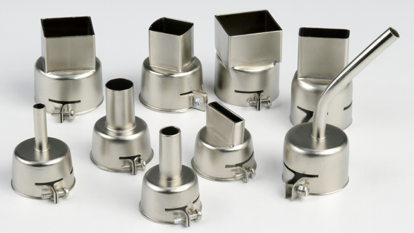
- The proper selection and design of interchangeable nozzles that direct the heated airflow to the component. (See Figure 2)
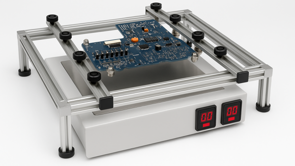
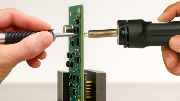
- Proper positioning of the circuit assembly during the removal process. (See Figure 3)
Nozzle Selection
Nozzles have evolved in design. The thinnest-walled nozzles work best since they can reach components on densely populated assemblies. A thick-walled nozzle might not fit, necessitating the time-consuming and tricky manual removal of adjacent components.
Many nozzles use a more open heating design than a fluted design that directs heat onto the component leads and away from the component body. A difference of opinion exists on whether outer edge heating is the most effective. Some will argue that double-walled nozzles, which direct heated air at the periphery of the component, avoid overheating the die itself and protect it from thermal damage.
The argument against outer edge heating maintains that the component is designed to see reflow temperatures. An argument that you can effectively heat the leads of a part, and not the body of the component package, to remove it may be asking for a challenge. The entire package reaches reflow temperature during the normal reflow cycle. And, if the part is defective and is being replaced, the point is moot.
Circuit Board Positioning
Positioning the circuit board during rework is also critical. Circuit boards should be properly positioned in a fixture before removal. Positioning means placing the circuit board so that it is perpendicular to the heating nozzle and at the correct distance below the nozzle.
If positioned too high, hot air will heat too wide an area and extend the dwell times. If placed too low, the nozzle efficiency is reduced, leading to possible overheating. Follow the hot air system manufacturer's instructions and experiment on your own with practice boards to find the best parameters for you.
Board Preparation
Often overlooked is board preparation -- a task as important as the rework process itself. Tape off or mask areas or components adjacent to the target component with high-temperature tape, metal shields, deflectors, or heat sinks to minimize the spread of heat to solder joints or plastic parts that should not see reflow temperatures.
Before applying these masks, which can be done quickly, pre-bake the circuit board assembly to remove moisture and minimize the potential for delamination, measling, or popcorning of components.
Preheating also shortens the ramp to reflow temperature, minimizing thermal stress on the board. The baking time may vary. Follow IPC guidelines.
Component Removal
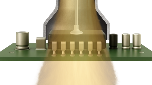
What do you do once the part is hot enough for removal? Vacuum wands or pens, integral to the machine or attached as a hand-held accessory, are generally used to remove components from the circuit board assembly once the solder has become molten. The gentle nature of a vacuum lift will usually prevent damage to surface-mount pads. While the vacuum grip is just firm enough to overcome the surface tension of molten solder and lift the component away, the grip will not hold if solid solder connections remain, except in cases of very fine pitch leads and tiny pads. (See Figure 4)
However, vacuum pens will certainly not pull away from a device that has been bonded with adhesive. Removal is more difficult, risking damage to the circuit board, and requires sturdier tools such as tweezers or dental-type probes.
The only way to remove adhesive-bonded components without destroying the board is to heat the board and component sufficiently to soften the adhesive, then gently and slowly pry the part off.
The peripheral leads may need to be lifted first to remove them from the pads and bend them upwards to avoid damaging the pads when the actual body of the component is pried or twisted loose.
Several members of the Circuit Technology Center team contributed to this feature story. Images may be altered or recreated to protect proprietary information.