|
This article deals with the occasional tendency of larger (and thinner) BGA components to warp during rework.
The warping addressed here can cause bridging and shorts at the outer corners of the device during replacement. This problem can require more rework at the BGA site, which is undoubtedly no fun at all.
It's generally understood that some minor distortion occurs in BGA components and circuit boards when heated due to the varying thermal coefficients of expansion (TCE) of the different materials. In the BGA component, this effect is most significant (or at least appears greatest) at the outermost edges. The larger the BGA package, the greater the warp at the outer corners.
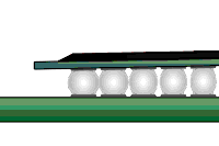
The warping can be very slight - in this case, the center of the BGA will bow upwards, and the corners will bow downwards. However, it's often enough to cause the corners to move closer to the circuit board surface, thereby putting extra pressure on the corner solder joints.
The result can be that the solder balls at the corners pancake to the point that they may touch and bridge with one another. (See Figure 1). It's worthwhile noting that the warping may also occur in the opposite direction, with the corners curling upward.
Once bridged or shorted, solder balls may remain in that condition due to the surface tension inherent in the molten solder. This problem is usually not detected until after rework, during X-ray inspection. At that point, you know the rework procedure was unsuccessful and must be repeated, subjecting the site to additional thermal cycles, which risks pad degradation and other problems.
Additionally, the circuit board itself may warp slightly, and this additional warp, when combined with that of the BGA, can exacerbate the problem. Of course, the first thing to examine is the profile itself, but even when profiles are tweaked, there can still be occasional problems at the corners due to the inherent limitations of the rework process.
The solution to this problem is simple yet effective, and we employ it whenever necessary. It merely involves providing the needed "support" for the outer corners of the BGA during the critical time that the BGA solder balls are molten.
Our method measures the clearance between the circuit board surface and the underside of the corner of a properly soldered BGA, like the one we will rework. We then select small pieces of non-solderable material to serve as spacers.
The thickness of these spacers is slightly less than the component stand-off height in its post-reflow state. Remember, the spacer is designed to prevent bridging, not to hold the component at a specific height above the board.
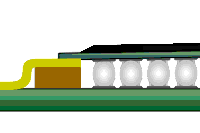
Once the old BGA has been removed, the site is prepared, and solder paste is applied to the pads on the board surface. We place these spacers at the four corners of the BGA site. They are held in place with a low-tack, heat-resistant, no-residue adhesive.
The edge of the spacer will fit under the edge of the BGA corner, and you would not want it to penetrate beneath the BGA far enough to disturb any solder connections. It's easy to place the spacers precisely since the pad area and paste print volume is easy to see, and you can gauge the distance visually to prevent contact between the spacer and the solder connection.
As the new BGA is ramped up to reflow temperature under a hot gas reflow machine nozzle, the spacers prevent the corners from flattening the balls underneath. (See Figure 2) As the BGA cools and the warp decreases, the outer edge balls solidify, and the solder connections beneath the center solidify.
Regarding whether curling of the edges causes issues with interior connections, we have observed no connection problems under the inner periphery of BGA connections (those that a slight warp would theoretically affect).
The shorting is the most pressing problem, and the spacers correct it. You can easily remove the spacers once the BGA and board have cooled to ambient temperature. Depending on your applications, equipment, or engineering support, you may or may not notice this condition, but now you have a solution if you do.
Several members of the Circuit Technology Center team contributed to this feature story. Images may be altered or recreated to protect proprietary information.
|
|
Related
|


