Outline
This procedure covers the robotic tinning of chip components.
Caution: Due to the need to completely control the rates of immersion and emersion of the chip component terminations and the dwell times in and between each process step, a robotic hot solder dip is recommended for chip component tinning. Semi-automatic or purely manual solder dipping processes may not be capable of completely controlling the rates of immersion and emersion of the chip component terminations and only provide approximate dwell dipping times in the solder bath. Greater variation in the process may cause a higher chance of damage, including latent reliability problems.
Minimum Skill Level - Expert
Recommended for technicians with advanced soldering and component rework skills and extensive experience in most repair/rework procedures.Conformance Level - High
This procedure most closely duplicates the physical characteristics of the original, and most probably complies with all the functional, environmental and serviceability factors.| Procedure References | |
| 1-0 | 1.0 Foreword |
| 11-1 | 11.1 Introduction to Component Lead, Pin, Pad, and Termination Conditioning and Tinning |
| 2-1 | 2.1 Handling Electronic Assemblies |
| 2-2 | 2.2 Cleaning Procedures |
| 2-5 | 2.5 Baking and Preheating |
Tools and Materials
Batch or inline cleaning system for removing fluxes and contamination. |
Disposable, puncture-resistant gloves designed for handling mild chemicals. |
Precision microscope with stand and lighting for work and inspection. |
General purpose oven for drying, baking and curing epoxies. |
Robotic system for component tinning and BGA solder ball removal. |
Protect your eyes and your vision with proper safety glasses. |
Used to prepare solder surfaces and to prevent formation of oxides during soldering. |
Multiple sizes and tip configurations of tweezers for various small parts handling needs. |
Manual or powered vacuum pickup tool for handling small parts and electrinic components. |
Nonabrasive, low-linting wipes for cleanup. |
Procedure
- Ensure the components meet the acceptable Moisture Sensitivity Level (MSL) for processing.
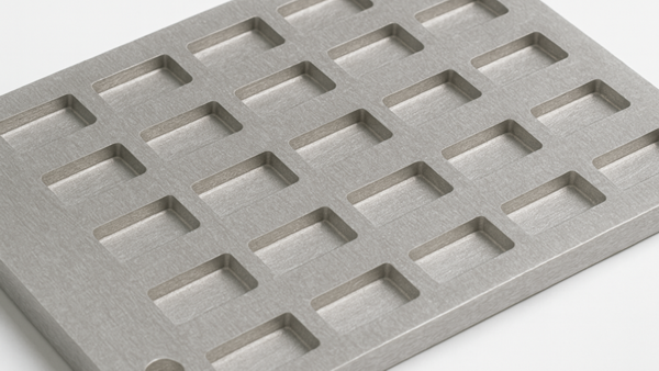
Note: For details on baking and moisture control, refer to Procedure 2.5 Baking and Preheating. - Use a matrix tray or fixture tray to position the components for pickup by the robotic tinning system. (See Figure 1)
- Set up the robotic tinning system with the proper process parameters, including solder immersion depth, dwell times, insertion and extraction speeds, solder temperature, and other settings. (See Figure 2)
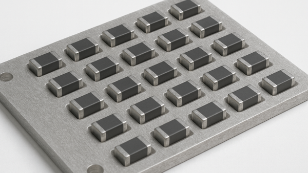
Note: Consult the component datasheet for peak temperature limits and other specific guidelines. - Place the components into the tray and position the tray in the system's staging area. (See Figure 3)
- Initiate the robotic tinning system's process cycle.
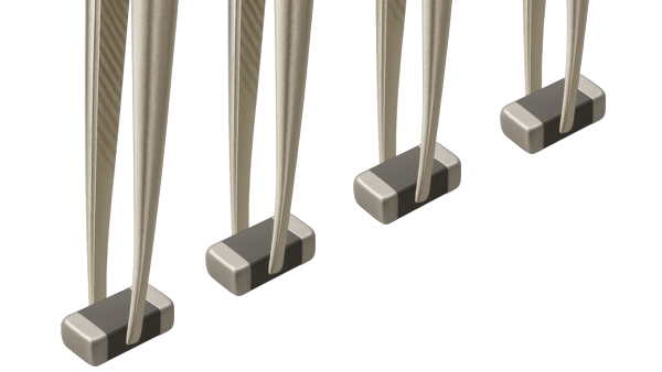
- The system will use a vacuum-pickup (single or multi-head) or mechanical grippers to retrieve one or more components from the tray. (See Figure 4)
- The system will apply flux to the terminations, then pass the components through a preheat stage to activate the flux and to prevent thermal shock to the components.
- The robotic arm will dip the terminations into the solder pot or solder wave and manipulate the components to ensure complete solder coverage.
- A filtered hot water rinse or other flux remover required by the flux type selected may be used to remove flux residues, followed by a drying cycle.
- After tinning, the system will return the tinned components to their original position in the matrix or precision-machined tray.
- As required, complete the cleaning by washing the components in a cleaning system.
- As required, dry the components in a general-purpose convection oven. Temperatures not to exceed 100°C. Note: this is not to be used as an MSL bake schedule.
- Visually inspect the components for appearance, cleanliness, and general condition. Confirm proper solder coverage on the terminations.
- As required before packaging and shipping, MSL dry-bake the components in a general-purpose convection oven according to the temperature and time requirements to meet the Mixture Sensitivity Level J-STD-003.
Evaluation
- Visual examination
- Tests or other inspection criteria as specified.
Images
Tinning, Chip/Discrete Components, Robotic Method
Use a matrix tray or fixture tray to position the components for pickup.
Set up the robotic tinning system with the proper process parameters.
Place the components into the tray and position the tray in the system's staging area.
The system will use a vacuum-pickup or mechanical grippers to retrieve one or more components from the tray.