Outline
The guide covers the general requirements for the reclamation of electronic components for reuse. These procedures differ slightly from those in prior documents covering Rework Procedures. Rework procedures focus on removing components with an emphasis on avoiding damage to the circuit board assembly. Salvaging the component for possible reuse is secondary.
The procedures in this section focus on removing components with an emphasis on avoiding damage to the component. Preventing damage to the circuit board assembly is secondary.
Note: Level of Conformance definitions for component reclamation differ from definitions in prior sections. These definitions are:
- based on the original electrical, functional, and environmental product requirements and serviceability factors.
- based on the skill of the technician.
- based on the capabilities of the manual, semi-automated, or automated equipment used.
- based on long-term industry experience.
- not necessarily backed up with testing data.
Consider levels of conformance relative to the type of processes that will meet the reclaimed components' original body, lead, pin, and terminations (such as solder spheres and metalized areas) specifications.
Levels of Conformance
- Lowest Level (L) - Reclaimed components may differ from the manufacturer's specifications (including physical appearance). They are not considered suitable for use with automated assembly equipment processing. The lowest level applies when the original manufacturer's data sheet does not provide detailed specifications or the datasheet is unavailable.
- Medium Level (M) - Reclaimed components may differ from the manufacturer's specifications (including physical appearance). Based on inspection and testing, reclaimed components may be suitable for use with automated assembly equipment processing.
- Highest Level (H) - Reclaimed components most closely meet all the manufacturer's specifications (including physical appearance). They are suitable for use with automated assembly equipment processing. For the highest level of conformance, there would be no physical alterations to the original component. A high-level process would involve dipping the leads in a solder pot using robotic equipment to provide precise timing of the component immersion and angle in the solder pot, thereby more closely matching the specifications stated by the component manufacturer.
Procedure
Hot Air Rework Systems
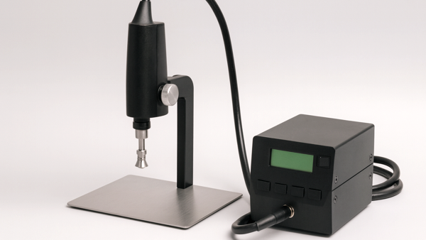
Hot gas rework systems and tools are commonly used for non-contact removal of surface mount components from circuit boards. These tools and systems direct precisely controlled, heated gas (usually air or nitrogen) through a nozzle to elevate the temperature of the component and solder joints to reflow levels, allowing clean component removal without physical damage to the board or neighboring parts.
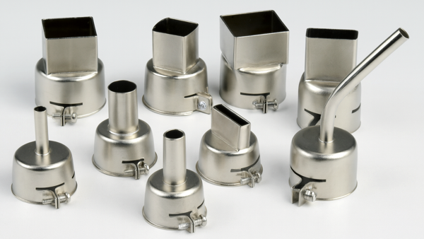
The nozzle size is based on the component's overall length and width. Some nozzle designs target only the leads and pad areas, while others heat the entire component body. Certain nozzles may include a vacuum assist to lift the component from the board surface after solder reflow. Users should verify the nozzle fit before processing.
Typical hot gas rework tools and systems include the following. (See Figures 1, 2, and 3)
- A controller unit to regulate the gas temperature, flow rate, and timing.
- Nozzles to direct hot gas onto the component; available in various shapes/sizes.
- An optional vacuum pickup tool to lift the component once the solder is reflowed.
- An optional preheater to warm the underside of the circuit board to reduce thermal stress.
- An optional positioning arm or XYZ table to allow precise alignment over the component.
Solder Fointain Systems
Most solder fountain systems have the same basic components. A solder pump and solder reservoir, various nozzle sizes, and controls for solder flow height. Solder from the reservoir is driven up through the nozzle by the pump. Nozzles are made of steel with welded seams and connections. The nozzle construction must allow for the capture of the pump's inflow and the runoff of the solder. This prevents the excess solder from splashing and maintains a usable solder level above the nozzle lip. Above the solder fountain head, there is generally a light projected alignment mark that permits you to center the part to be removed over the nozzle. (See Figures 4 and 5)
- Solder Height Adjustment
Solder height should be set at 1.50 mm - 3.00 mm (.060" - .120") above the lip of the nozzle. The ideal situation is to have the leads of a component just immersed and wetted without having the wave exert any upward pressure on the circuit board. The solder fountain table surface should be parallel to the nozzle surface. Components and leads on the bottom side of the circuit board may cause the PC board to be uneven; this condition must be compensated for. Insufficient immersion will prevent proper heat transfer and reflow. Excess pressure will cause the solder to surge up through the holes and spill out onto the top side of the circuit board.
- Solder Temperature Adjustment
Solder temperature adjustment varies depending on various factors. Normal setting 260 °C (500°F). During heavy use, solder temperature may cycle between 250 °C - 270 °C (480°F - 520°F). The heaters should react quickly to normal drops in temperature. The heaters may overshoot the preset temperature when vigorous activity is suddenly halted. Operators must be alert to temperature fluctuations that exceed preset standards.
- Solder Fountain Time Adjustment
This adjustment can be used to precisely control repetitive operations or in instances where you want to strictly control a circuit board's exposure to the solder fountain heat. The timer may also be set to maximum, and the wave's on/off action is controlled by the motor on/off foot pedal or by lifting the board on and off the wave.
- Component Removal Tools
There are a variety of removal tools to help extract the component once reflow has been achieved. The extractor tool should provide the operator with a good grip but should not unduly damage the component during removal.
Manual Desoldering Tools
A powered vacuum desoldering tool is commonly used to remove solder from through-hole joints for component salvage or rework. These tools combine a heated tip to melt solder and a vacuum pump to extract molten solder, clearing the plated hole and freeing the component lead. (See Figure 6)