How to Use a Solder Fountain
[unknown placeholder $article.blog_tech_summary$]
REQUEST FOR QUOTE BLOGS INDEX
|
|
22 Parkridge Road Haverhill, MA 01835 USA www.circuitrework.com |
Rework departments often encounter large through-hole components on high-mass circuit boards or components with heat sinks. The solder fountain machine is ideal for this type of rework. With the introduction of lead-free solders, the use of solder fountains has increased.
Solder Fountain Pros and Cons
A solder fountain can transfer large amounts of heat to a specific area very quickly. A typically laborious and time-consuming procedure with a desoldering tool is completed rapidly and relatively easily.
However, the strength of the solder fountain system is also its chief danger. Solder can overflow or spatter, which presents the possibility of serious injury. Safety is the primary concern when using one of these machines.
A solder fountain transfers considerable thermal energy to both the circuit board and the component by direct contact and heat transfer by molten solder. Printed circuit board materials are susceptible to damage such as layer delamination, copper delamination, separation of pads or barrels from inner layers, burns, solder mask damage, and warpage. If several circuit boards require rework, a few should be carefully evaluated until a reliable procedure is established.
Solder Fountain System
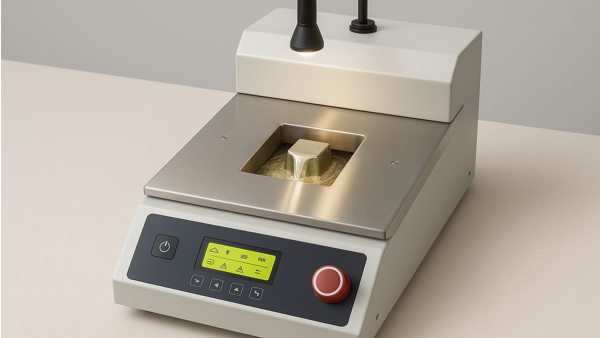
Think of a solder fountain as a mini wave-soldering machine without a conveyor. Similar components - a solder pump and reservoir, various interchangeable nozzles of different sizes, and controls for solder flow height - can be found in the system. (See Figure 1)
Solder Height Adjustment
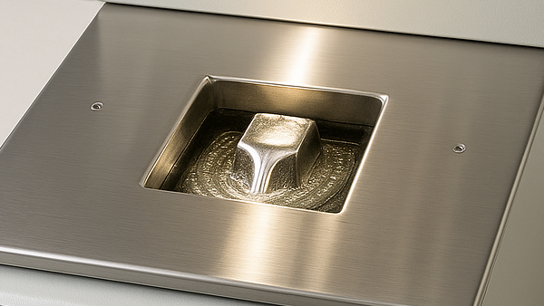
Solder height should be set at 1.50 to 3.0 mm (0.060 to 0.120 in.) above the lip of the nozzle. Ideally, the leads of a component should be immersed and wetted without having the wave exert any upward pressure on the circuit board. The solder fountain table surface should be parallel to the nozzle surface.
Components and leads on the bottom side of the circuit board may cause the circuit board to be uneven, which must be corrected. Insufficient immersion will prevent proper heat transfer and reflow. Excess pressure will cause the solder to surge up through holes and spill onto the top side of the circuit board - a potentially hazardous situation for the operator and circuit board. (See Figure 2)
Temperature Adjustment
Solder temperature adjustment varies depending on various factors, including the melting point of the solder, and will be higher for lead-free alloys. The standard setting for tin/lead solders is 260 °C, 500°F. During heavy use, solder temperature may cycle between 250 and 270 °C.
The heaters should react quickly to normal drops in temperature. Heaters may overshoot the preset temperature when vigorous activity is suddenly halted. Operators must be alert to temperature fluctuations that exceed preset standards.
Time Adjustment
This adjustment can be used to precisely control operations of a repetitive nature or in instances where a circuit board's exposure heat must be strictly controlled.
Removal Tool
Various removal tools exist to help extract the component once reflow has been achieved. The extractor tool should give the operator a good grip but not unduly damage the component during removal. However, sometimes a tool is not workable, and the operator must use a gloved hand. See Figure 3.
Circuit Board Pre-heat
The standard recommendation for pre-heat is 1 to 4 hours at 65 to 120 degrees C (150 to 250 degrees F). The temperature and time requirements for pre-heat depend on the board construction, age, and exposure to the atmosphere.
Board Preparation
Before rework, the operator should straighten any component leads, which may prevent the easy removal of the component, and mask the area surrounding the component to be removed if protection is needed. An operator may need to mask components with high-temperature tape or a high-temperature flexible mask. The mask may need baking to provide the proper cure before reflow.
Rework
Some final tips: