Soldering to gold has never been a flawless exercise. Concerns about the quality and quantity of gold finishes buzz around the soldering process like annoying horseflies, drawing blood whenever your guard is dropped.
Soldering gold connector pins into through-holes can impose additional constraints on the allowable height of solder fillets along the length of the gold pins. Beyond initial manufacture, the rework of these same through-hole gold connectors, that is, removing and replacing them by hand, is exceptionally challenging.
It's challenging to get solder to flow down into holes to sufficiently wet gold pins while keeping it from running upward into a pin's restricted zone. The longer a hot soldering iron tip dwells on the connector pin to complete the solder joint, the more likely it is that some solder will wick up the pin.
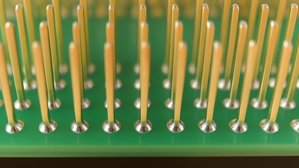
We had a particularly daunting application arrive at our facility. Not only were the pins gold, but the board was stacked with heavy ground planes, and the pins were four rows deep. (See Figure 1)
Using the usual packet of rework tricks, expert technicians could solder 50 to 75 percent of the pins manually, but a few locations would stubbornly resist every effort. To succeed, we had to try something different.
There were four key performance targets:
- Acquiring access to the inner rows of pins while delivering sufficient heat and not contaminating adjacent pins with solder.
- Wetting the gold surface of the pins.
- Wetting the walls of the plated through holes.
- Maintaining the topside solder fillet below the specified height.
To meet these targets, a variety of techniques were applied. Using a mini-wave system, the connectors were removed from the board. Then, the plated-through holes were cleared with vacuum desoldering tools. A good deal of attention was paid to this process, as one of the main reasons for the rework was the lack of wetting in the plated-through holes. After solder removal, the plated holes were carefully inspected with a microscope and back-light.
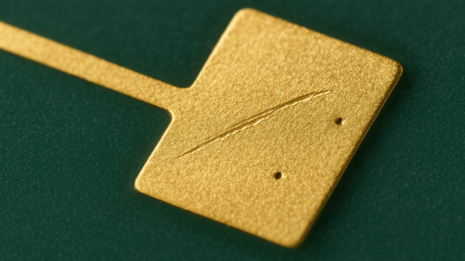
Once the connector locations were fully inspected, a combination of hand and convection soldering was used to access the pins. Control of solder volume was essential to ensuring proper fill and preventing unacceptable solder wicking up the pins. This was accomplished at challenging locations by adding pre-manufactured solder preforms. (See Figure 2)
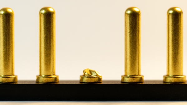
All in all, a pretty time-consuming process, but sometimes that's what it takes to be successful in rework. As you can see, the time was well spent, and the results were excellent. (See Figure 3)
Several members of the Circuit Technology Center team contributed to this feature story. Images may be altered or recreated to protect proprietary information.