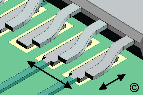
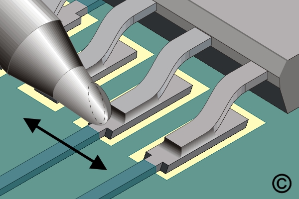
7.5.2 Soldering Surface Mount Gull Wing Components, Continuous Flow Method
Install gull wing components using continuous flow soldering methods. Learn process control techniques that promote consistent solder fillets and electrical integrity.
REQUEST FOR QUOTE GUIDES INDEX