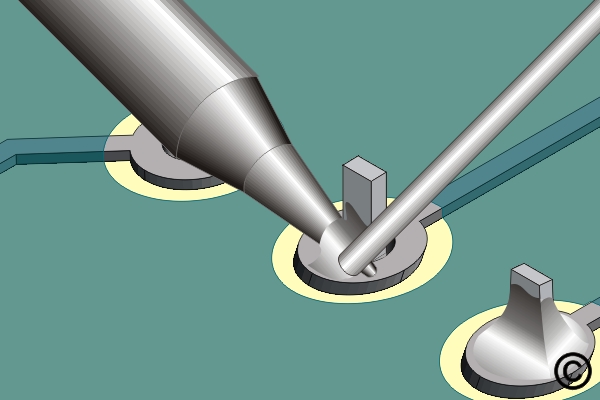
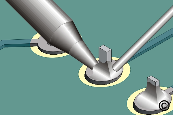
7.2.1 Soldering Through Hole Components, Point To Point Method
Solder through-hole components using the point-to-point method for precise heat application. Covers lead preparation, solder flow and inspection practices for dependable connections.
Minimum Skill Level: Intermediate
Conformance Level: Medium
REQUEST FOR QUOTE GUIDES INDEX