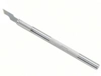
4.2.3 Conductor Repair, Welding Method
Reconnect damaged conductors using micro welding techniques. Covers equipment control, alignment and inspection practices for permanent electrical restoration.
Minimum Skill Level: Advanced
Conformance Level: High
REQUEST FOR QUOTE GUIDES INDEX