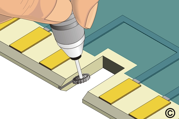
3.4.2 Key and Slot Repair, Transplant Method
Restore keys and slots using laminate transplant procedures for severe damage. Covers controlled material removal, insert fabrication and bonding to ensure mechanical strength and alignment.
Minimum Skill Level: Expert
Conformance Level: High
REQUEST FOR QUOTE GUIDES INDEX