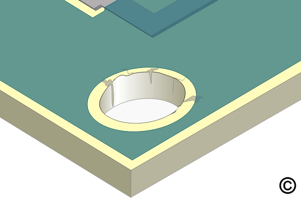
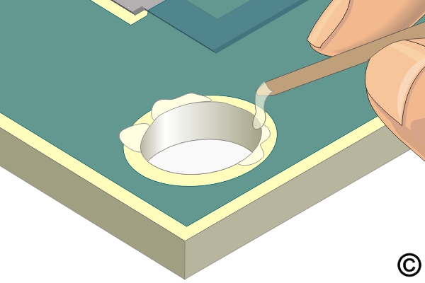
3.3.1 Hole Repair, Epoxy Method
Restore non-functional holes in circuit boards using epoxy fill techniques. Covers preparation, material selection and curing methods to rebuild structural integrity while maintaining board reliability.
Minimum Skill Level: Advanced
Conformance Level: High
REQUEST FOR QUOTE GUIDES INDEX