Outline
This procedure covers the robotic tinning of gull wing components.
|
|||||||||||||||||||||||||||||||||||||||
Procedure
Procedure
Evaluation
|
|||||||||||||||||||||||||||||||||||||||
Images and Figures![]() Tinning, QFP/PLCC Components, Robotic Method
![]() Figure 1. Use a matrix tray or fixture tray to position the components for pickup.
![]() Figure 2. Set up the robotic tinning system with the proper process parameters.
![]() Figure 3. Place the components into the tray and position the tray in the system's staging area.
![]() Figure 4. The system will use a vacuum-pickup to retrieve one or more components from the tray.
|
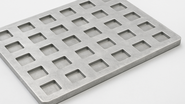
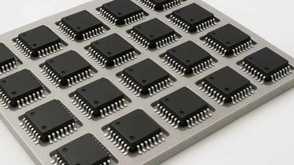
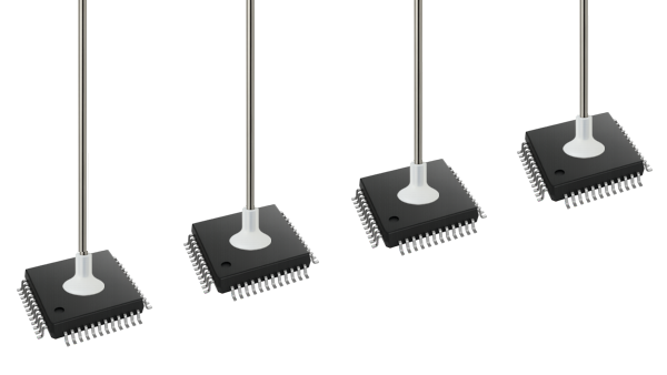
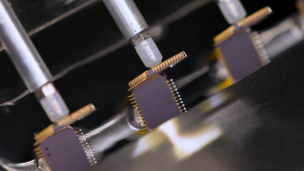
11.6 Component Lead Conditioning and Tinning, Gull Wing Components
This procedure covers robotic tinning of gull wing components, including QFP and PLCC components.
Minimum Skill Level: Expert
Conformance Level: High
REQUEST FOR QUOTE GUIDES INDEX

Tinning, QFP/PLCC Components, Robotic Method

Use a matrix tray or fixture tray to position the components for pickup.

Set up the robotic tinning system with the proper process parameters.

Place the components into the tray and position the tray in the system's staging area.

The system will use a vacuum-pickup to retrieve one or more components from the tray.

Our robotic component tinning systems modify component leads and terminations with precision and repeatability.
LEARN MORE
SLIDESHOW STARTING
❮
❯