| Feature |
Dim |
Class 1 |
Class 2 |
Class 3 |
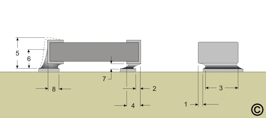
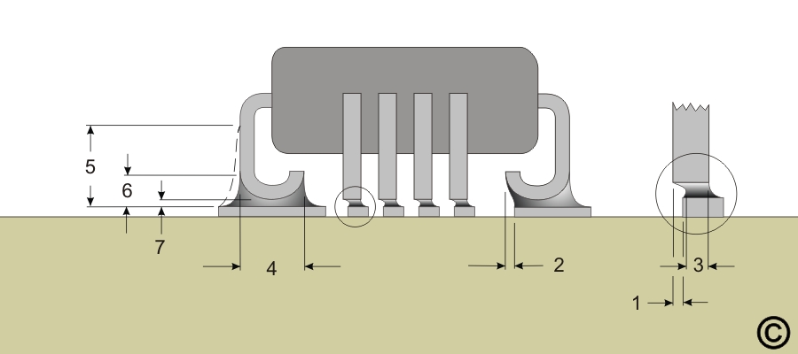
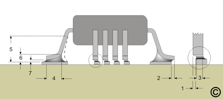
| Maximum Lead Side Overhang |
1 |
No more than 50% of the lead width or 0.50 mm (.020"), whichever is less. |
No more than 50% of the lead width or 0.50 mm (.020"), whichever is less. |
No more than 25% of the lead width or 0.50 mm (.020"), whichever is less. |
| Maximum Toe Overhang |
2 |
Does not violate minimum electrical clearance. |
Not acceptable. |
Not acceptable. |
| Minimum End Joint Width |
3 |
50% of the lead width. |
50% of the lead width. |
75% of the lead width. |
| Minimum Side Joint Length: Lead thickness greater than 3X lead width |
4 |
Equal to the lead width or 0.50 mm (.020"), whichever is less. |
3 times the formed foot length or 75% of the formed foot length, whichever is longer. |
3 times the formed foot length or 75% of the formed foot length, whichever is longer. |
| Minimum Side Joint Length: Lead thickness less than 3X lead width |
4 |
Equal to the lead width or 0.50 mm (.020"), whichever is less. |
Equal to 100% of the formed foot length. |
Equal to 100% of the formed foot length. |
| Maximum Heel Fillet Height |
5 |
No maximum, but solder must not touch the component package body. |
No maximum, but solder must not touch the component package body. |
No maximum, but solder must not touch the component package body. |
| Minimum Heel Fillet Height |
6 |
Evidence of proper wetting. |
Equal to the solder thickness plus 50% of lead thickness. |
Equal to the solder thickness plus 100% of lead thickness. |
| Solder Thickness |
7 |
Evidence of proper wetting. |
Evidence of proper wetting. |
Evidence of proper wetting. |