Cutting Circuits and Conductors
[unknown placeholder $article.blog_tech_summary$]
REQUEST FOR QUOTE BLOGS INDEX

|
|
22 Parkridge Road Haverhill, MA 01835 USA www.circuitrework.com |
Performing cuts on external and internal connections can be simple or highly complex.
Quite often, a rework department is confronted with the task of cutting, rather than establishing, connections. Usually called conductor cuts or circuit cuts, such procedures involve breaking connections both on the surface of the circuit board and internally.
Why do these cuts need to be made? Why do connections on or in boards need to be severed? Design changes drive these types of procedures that may, for example, make the function of a circuit assembly more efficient.
Sometimes artwork has not been laid out correctly, and faults that need to be corrected will exist after the board has been manufactured. Tools used for these procedures can include precision knives, micro drills with ball mills, precision drill systems with end mills, and customized tools.
A Simple Procedure
Performing circuit cuts can be simple or highly complex. A circuit cut is a simple matter when the circuit to be cut is on the surface of the circuit board. For example, the procedure for making a typical surface circuit cut, used to sever a circuit or a short, is a simple one. A small section of the circuit is removed, forming a break, typically with a knife (See Figure 1) or high-speed micro-drill (See Figure 2).
In this instance, the operator makes two small parallel cuts perpendicular to the path of the conductor, cutting only as deep as the conductor. The width of the break should be at least the minimum conductor spacing. After cutting, the area is sealed with epoxy.
Inner Layer Circuit Cuts
Severing inner-layer circuitry is more complicated. In this instance, the exact location of the inner layer must be determined, sometimes with bright back-lighting, but, more often (with thicker boards), through x-ray technology.
Determining the precise cut location is critical - one does not want to drill down and destroy other circuitry while attempting to reach the connection that needs to be cut.
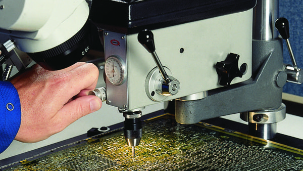
Once the cut location is established, the board must be secured in position, or fixtured. A precision drill system and carbide end mill, slightly larger in diameter than the width of the conductor, is then used to cut into the board at the proper coordinates - down to the conductor and just through it - to sever the connection. (See Figure 3)
The hole is then filled with epoxy. When dealing with any of these cuts, internal or external, precise depth control is critical.
Extreme care must be taken to prevent damage to adjacent or underlying inner-layer circuits. A microscope must be used during milling when extreme accuracy is required.
Remember that, with many multilayer boards, the distance between inner layers can be small, often no more than 0.127 mm (0.005 in.). One does not want to cut too deeply and sever additional and unintended connections.
The operator should withdraw the drill frequently to remove debris and look into the hole with the aid of a microscope and high-intensity lighting. Bear in mind that differences between the artwork and the actual manufactured printed circuit board can exist.
You should be able to establish the two-dimensional location of a connection with an X-ray, but depth is another matter, and PCBs can vary tremendously. Another method to determine when a cut is completed is to use an ohmmeter connected to either end of the conductor to be cut; once the cut is completed, the meter will indicate the disconnect.
Through-Hole Connections
In some cases, it may be necessary to break an internal connection made by a plated-through hole. In such a case, the removal of the plated through-hole barrel is the way to break the connection.
This procedure is performed with a precision drill system and an end mill slightly larger than the plated-through hole itself. The hole is, again, filled with epoxy flush with the surface of the PCB. The hole may then be re-drilled to the diameter needed.
Sometimes, an internal layer that must be disconnected from a plated through hole (PTH) is connected via a spoke pattern - the method for disconnecting is called a spoke cut. In this instance, the user drills down with an end mill through the board, adjacent to the perimeter of the hole, to a specific depth and severs the spokes of the inner layer connection.
The procedure is extremely precise work. The cutting tool should be approximately 0.010 to 0.025 mm (0.005 to 010 in.) greater than the width of the spoke or circuit to be cut. Afterward, the holes may be filled with epoxy, but only after the technician has determined that all necessary spokes have been completely cut and that no other circuitry has been inadvertently damaged.