Circuit Technology Center
SEARCH  

6.5 Component Trim and Form

Outline
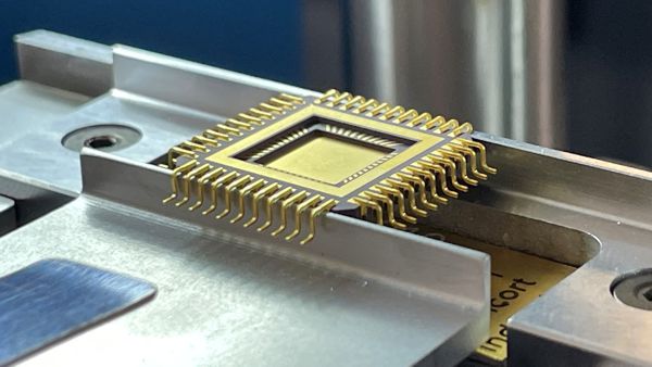
This procedure covers the general guidelines for trimming and forming electronic component leads. Components may be supplied in a frame configuration and need to be trimmed and formed to meet requirements to match component footprint patterns on circuit boards.

Minimum Skill Level - Expert
Recommended for technicians with advanced soldering and component rework skills and extensive experience in most repair/rework procedures.

Conformance Level - High
This procedure most closely duplicates the physical characteristics of the original, and most probably complies with all the functional, environmental and serviceability factors.

Acceptability References
IPC-A-610 Acceptability of Electronic Assemblies
Procedure References
1.0 Foreword
2.1 Handling Electronic Assemblies
2.2 Cleaning
Additional Items and Supplies
Microscope
Microscope
Precision microscope with stand and lighting for work and inspection.
Trim Form Machine
Trim Form Machine
Machine and dies to trim and form electronic components.
Solder Pot
Vacuum Pickup Tool
Manual or powered vacuum pickup tool for handling small parts and electrinic components.
Images and Figures
6.5 Component Trim and Form
Component Trimmed and Formed
6.5 Component Trim and Form
Figure 1. Component trim and form drawing.
6.5 Component Trim and Form
Figure 2. Component with outer tie-bar frame.

6.5 Component Trim and Form
Figure 3. Component trim and form machine.
Caution: This process may use automated, semi-automated, and manual trimming and forming machines. Operators should use appropriate safety procedures and safety equipment to prevent injury.

Caution: Trimming and forming equipment may use compressed air. Trimming and forming machines often use safety locks that require two-handed operation to activate. If the operator should remove their hands from these buttons during operation, the cylinder ram will retract and automatically return to the home position. During the production cycle, the operator should visually verify the stroke cycle's completion, ensuring the cylinder ram comes to a complete stop.

Procedure
  1. Obtain the component to be formed and determine the finished component lead formed dimensions. (see Figure 1.) These dimensions are usually shown on the circuit board assembly drawing.
  2. Verify all dimensions using appropriate documents, measuring tools, and equipment.
  3. If the component being processed has a plastic tie bar or frame, it may be necessary to trim this tie bar before processing. (See Figure 2.)
  4. Place the component in the cutting/forming area using a vacuum pen. Ensure the position is appropriate.
  5. Simultaneously press the two activation switches on the trim and form machine. Allow the machine to complete its cycle and return to the up position before releasing the switches. (See Figure 3.)
  6. Repeat the process. The component may require rotation to process component leads on adjacent or opposing sides.
  7. Remove the part and place it in ESD-safe packaging for further processing or transport.
Evaluation
  1. Visual examination.
  2. Tests or other inspection criteria as specified by customer drawings.
Procedure for reference only.