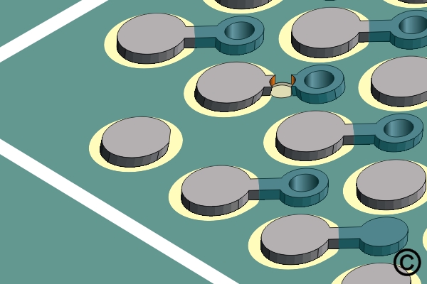
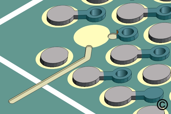
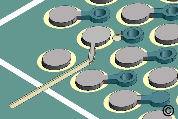
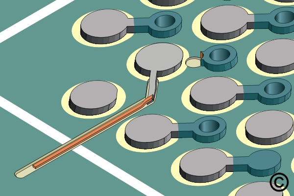
6.2.1 Jumper Wires, BGA Components, Circuit Track Method
Install jumper wires at BGA locations using circuit track methods for precise signal routing. Covers pad access, trace attachment and protection techniques for high-density assemblies.
REQUEST FOR QUOTE GUIDES INDEX