Outline
This procedure covers reballing of BGA components.
Minimum Skill Level - Expert
Recommended for technicians with advanced soldering and component rework skills and extensive experience in most repair/rework procedures.Conformance Level - High
This procedure most closely duplicates the physical characteristics of the original, and most probably complies with all the functional, environmental and serviceability factors.| Procedure References | |
| 1-0 | 1.0 Foreword |
| 2-1 | 2.1 Handling Electronic Assemblies |
| 2-2 | 2.2 Cleaning Procedures |
| 2-5 | 2.5 Baking and Preheating |
| 9-1-3 | 9.1.3 BGA Component Reball Inspection |
Tools and Materials

General purpose cleaner for removing contamination. |

Disposable brushes for solvent cleaning and application of coatings. |

Batch or inline cleaning system for removing fluxes and contamination. |

Woven copper wire designed to wick solder from surfaces and holes. |

Swabs for use with solvents and application of color agents and epoxies. |

Disposable, puncture-resistant gloves designed for handling mild chemicals. |

Precision microscope with stand and lighting for work and inspection. |

Small reflow oven for controlled solder reflow. |

General purpose oven for drying, baking and curing epoxies. |

Nine precision-crafted tools for detailed circuit board work. |

Protect your eyes and your vision with proper safety glasses. |

Used to prepare solder surfaces and to prevent formation of oxides during soldering. |

Solder paste for component soldering and rework. |

Solder balls or spheres for BGA component reballing and rework. |

Properly maintained soldering iron and properly sized soldering iron tips. |

Multiple sizes and tip configurations of tweezers for various small parts handling needs. |

Nonabrasive, low-linting wipes for cleanup. |
Procedure
Procedure - Solder Braid Ball Removal
- Ensure all BGA components to be processed meet the requirements for acceptable moisture levels.
Note: For information on baking and moisture level control see 2.5 Baking and Preheating - Remove existing solder spheres on BGA components using desolder braid. Place the de-solder braid on the balls to be removed, and gently place the soldering iron on the desoldering braid. Apply very light pressure to melt the solder balls. As the solder melts, capillary action will draw it onto the copper desoldering braid. Repeat as needed to remove all the solder balls. (See Figure 1) When complete, simutaneously lift both the soldering iron and solder braid. (See Figure 2)
- Clean the BGA components with an approved cleaning solution. The customer or contract may specify specific cleaning solutions. A typical cleaning process may use a cleaning brush and cleaner. Gently brush the surface until all evidence of flux and debris has been removed. Dry with a clean wipe or blow dry using an air gun.
Procedure - Mini-Oven Attachment
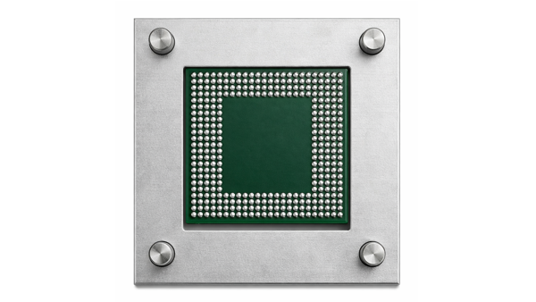
- Apply tacky flux to the flat BGA component pads using a brush. Flux should be evenly applied across the entire BGA pad surface. Use minimal flux needed to cover the surface fully. Remove any excess flux. (See Figure 3)
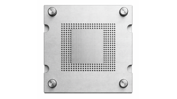
- Place the BGA components into a fixture and cover with a matching stencil. Check to ensure the alignment is correct. (See Figure 4 and 5)
- Place a quantity of the appropriate size solder spheres into the fixture and use a clean cleaning brush to distribute them so they fill all the open apertures in the BGA component stencil. Ensure all the apertures are filled with only one solder sphere. Tilt the fixture and pour the excess solder spheres into a collection container for reuse.
Note: Avoid overloading the solder stencil with excess solder spheres, as they may wedge under the stencil. This will make lifting the stencil to remove any excess solder spheres difficult. - Place the component and fixture into the mini BGA reflow oven. (See Figure 6)
- Turn the Mini BGA reflow oven on and select the proper profile.
Note: If a profile has not been defined, a profile will need to be created. - Close the cover of the Mini BGA reflow oven and press the start button. The oven will undergo the required preheat, reflow, and cooling cycles.
- When the temperature has cooled below 100 °C, use gloves and remove the reball fixture from the mini BGA reball oven once. Allow the fixture and components to cool for one minute to ensure package thermal stability before removing the BGA component from the fixture.
- Inspect the BGA component balls for proper alignment and appearance.
- Clean the BGA components in the approved cleaning solution.
- Inspect the body of the BGA component for abnormalities.
- Inspect the BGA component for cleanliness.
Images
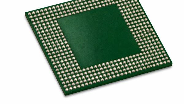
BGA Component Reballing, Braid Ball Removal, Mini-Oven Attachment Method
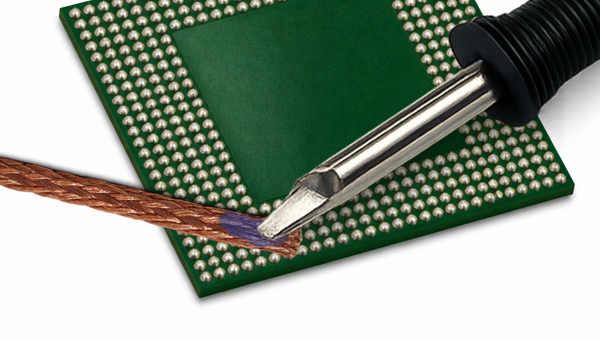
Remove the existing solder spheres on BGA components using desolder braid.
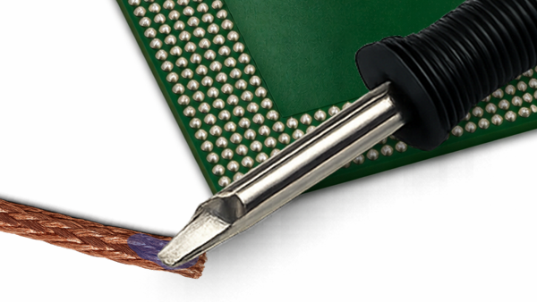
When complete, simutaneously lift both the soldering iron and solder braid.
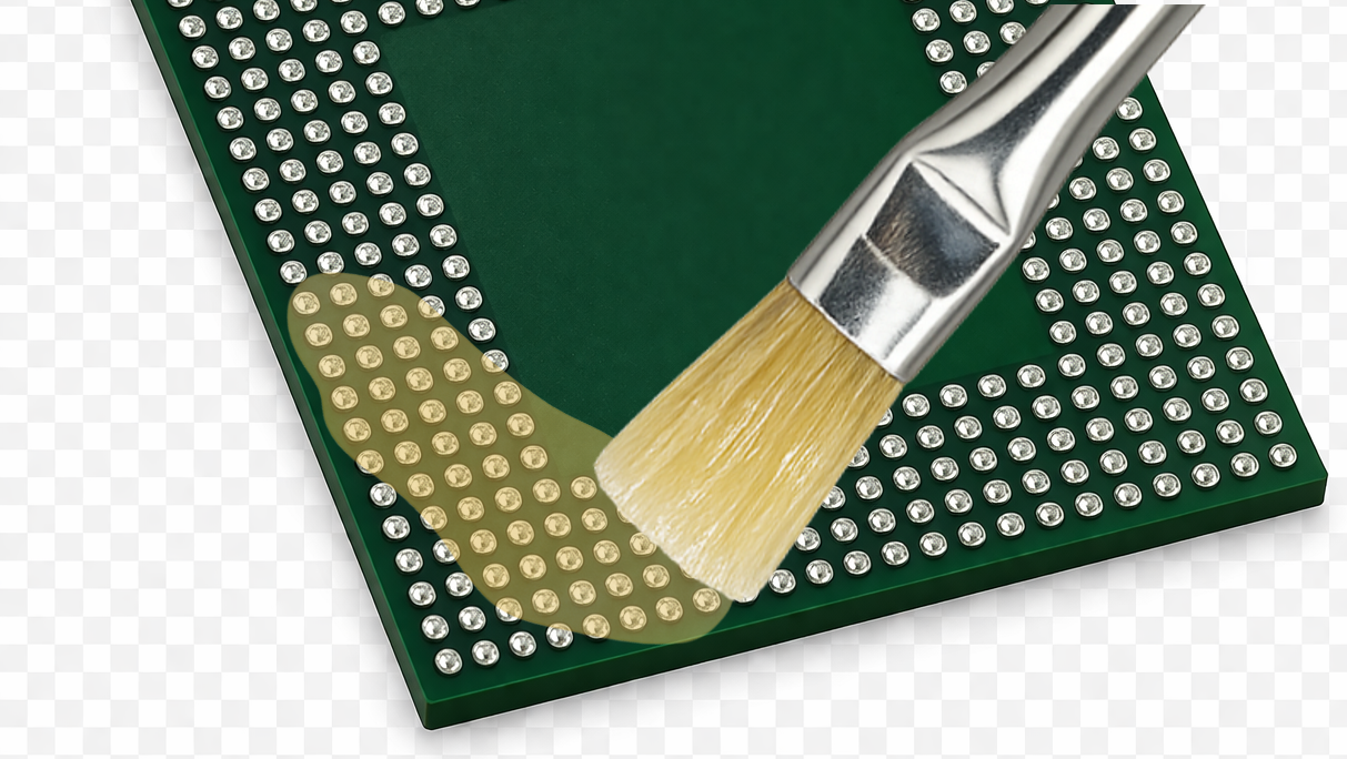
Apply tacky flux to flat BGA component pads using a brush.
Place the BGA component into a fixture.
Place the proper stencil on the fixture and fill the stencil apertures with the proper size solder balls.
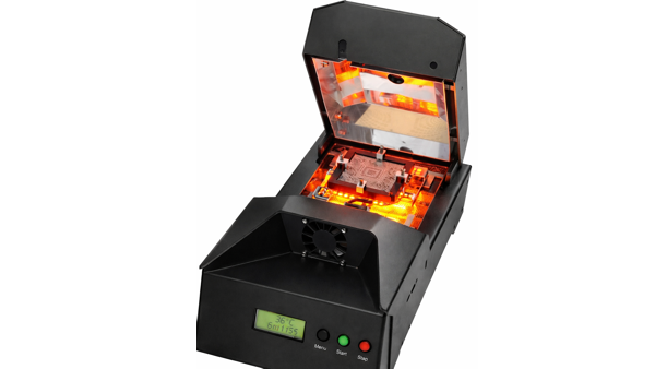
Place the component and fixture into the mini BGA reflow oven.