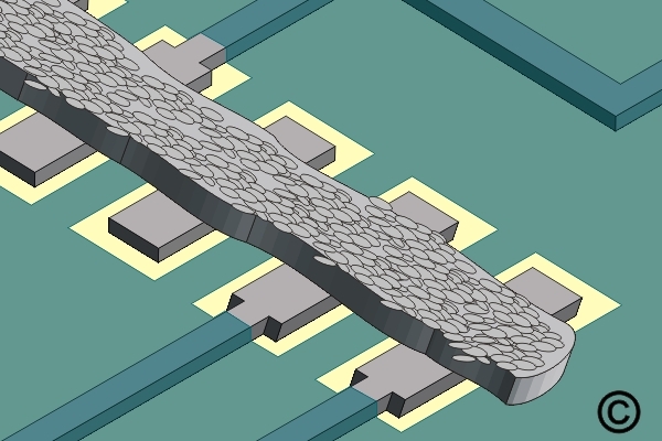
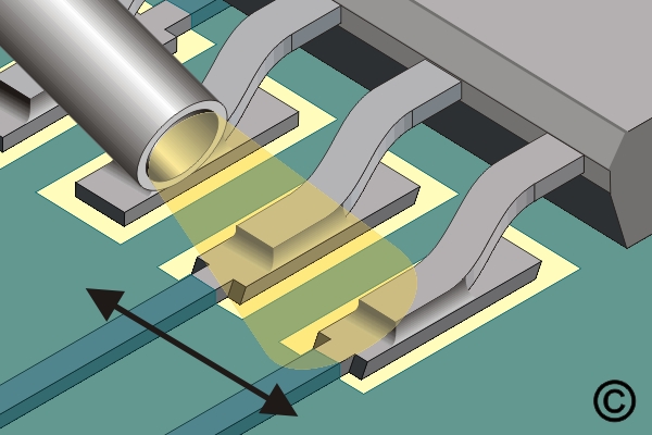
7.5.3 Soldering Surface Mount Gull Wing Components, Hot Gas Method
Solder gull wing components using hot gas reflow methods. Covers temperature profiling, airflow management and inspection practices for high-quality surface mount results.
Minimum Skill Level: Intermediate
Conformance Level: High
REQUEST FOR QUOTE GUIDES INDEX