Outline
This procedure covers the general guidelines for soldering surface mount Gull Wing components. There is basically only one type of Gull Wing component. Whether leads are on two sides or four sides, or whether the component is large or small, the soldering principles are the same.
Minimum Skill Level - Intermediate
Recommended for technicians with skills in basic soldering and component rework, but may be inexperienced in general repair/rework procedures.Conformance Level - High
This procedure most closely duplicates the physical characteristics of the original, and most probably complies with all the functional, environmental and serviceability factors.| Procedure References | |
| 1-0 | 1.0 Foreword |
| 2-1 | 2.1 Handling Electronic Assemblies |
| 2-2 | 2.2 Cleaning Procedures |
| 2-5 | 2.5 Baking and Preheating |
| 7-1-1 | 7.1.1 Soldering Basics |
| 7-1-2 | 7.1.2 Preparation For Soldering And Component Removal |
| 7-1-3 | 7.1.3 Solder Joint Acceptance Criteria |
Tools and Materials

General purpose cleaner for removing contamination. |

Sturdy rack for PCBs used for rework and positioning. |

Precision microscope with stand and lighting for work and inspection. |

Nine precision-crafted tools for detailed circuit board work. |

Properly maintained soldering iron and properly sized soldering iron tips. |

Training kit to practice circuit board soldering skills prior to testing for certification. |

Nonabrasive, low-linting wipes for cleanup. |
Procedure
Procedure
- Add liquid flux to the corner pads.
- Place the component in position and hold it steady. The leads must be aligned with the pads. On large components, this is best done by aligning the leads on opposite corners. (See Figure 1)
- Place the soldering iron tip at the junction between the pad and component lead at one of the corners. Apply additional solder as needed.
- Remove the tip. Wait a moment for the solder to solidify before soldering the opposite corner.
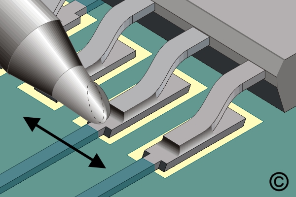
- Apply solder to the continuous flow solder tip to create a convex bead of molten solder on the tip. (See Figure 2)
- Position the solder tip so that the solder bead contacts the top portion of the leads. Slowly move the tip over the row of leads to form proper solder fillets at each joint. (See Figure 3)
- Repeat steps 5 and 6 for the remaining sides.
- Clean, if required, and inspect.
Images

Soldering Surface Mount Gull Wing Components, Continuous Flow Method
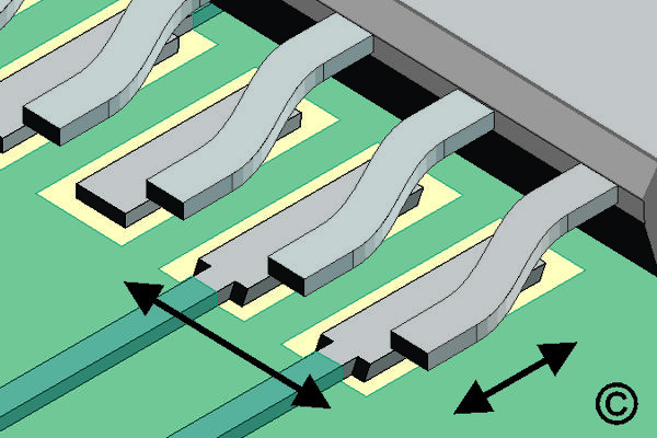
Place component and check alignment.

Apply solder to the continuous flow solder tip to create a convex bead of molten solder
Slowly move the tip over the row of leads to form proper solder fillets at each joint.