Outline
This procedure covers the general guidelines for soldering surface mount J lead components. There is basically only one style of J lead component. Whether leads are on two sides or four sides, or whether the component is large or small, the soldering principles are the same.
Minimum Skill Level - Intermediate
Recommended for technicians with skills in basic soldering and component rework, but may be inexperienced in general repair/rework procedures.Conformance Level - High
This procedure most closely duplicates the physical characteristics of the original, and most probably complies with all the functional, environmental and serviceability factors.| Procedure References | |
| 1-0 | 1.0 Foreword |
| 2-1 | 2.1 Handling Electronic Assemblies |
| 2-2 | 2.2 Cleaning Procedures |
| 2-5 | 2.5 Baking and Preheating |
| 7-1-1 | 7.1.1 Soldering Basics |
| 7-1-2 | 7.1.2 Preparation For Soldering And Component Removal |
| 7-1-3 | 7.1.3 Solder Joint Acceptance Criteria |
Tools and Materials

General purpose cleaner for removing contamination. |

Sturdy rack for PCBs used for rework and positioning. |

Includes materials to protect heat sensitive area of a PCB during rework. |

Tool and nozzles to deliver precise flow of hot air. |

Precision microscope with stand and lighting for work and inspection. |

Nine precision-crafted tools for detailed circuit board work. |

Solder paste for component soldering and rework. |

Training kit to practice circuit board soldering skills prior to testing for certification. |

Nonabrasive, low-linting wipes for cleanup. |
Procedure
Procedure
- Add a small bead of solder paste along the row of pads. (See Figure 1)
- Place the component in position.
- Adjust the pressure and temperature output of the hot air tool.
- Direct the hot air over the component with the hot air tool tip approximately 2.50 cm (1.00") from the solder joint. This initial heating will pre-dry the solder paste.
Note: Solder paste has a dull, flat appearance when dried. - When the solder paste has dried, move the hot air tooltip to approximately 0.50 cm (0.20") above the component. Move the tool back and forth to heat all the solder joints until complete solder melt is observed. (See Figure 2)
- Remove the tool. Wait a moment for the solder to solidify.
- Clean, if required, and inspect.
Images

Soldering Surface Mount J Lead Components, Hot Gas Method
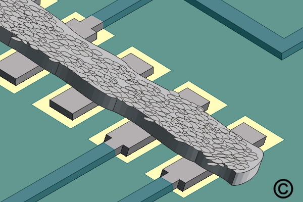
Add a small bead of solder paste along the row of pads.

Move the tool back and forth to heat all the solder joints until complete solder melt is observed.