4.3.2 Circuit Cut, Inner Layer Circuits
Isolate inner layer connections using controlled access and cutting techniques. Includes laminate entry, trace interruption and restoration procedures.
REQUEST FOR QUOTE GUIDES INDEX


|
22 Parkridge Road Haverhill, MA 01835 USA www.circuitrework.com |
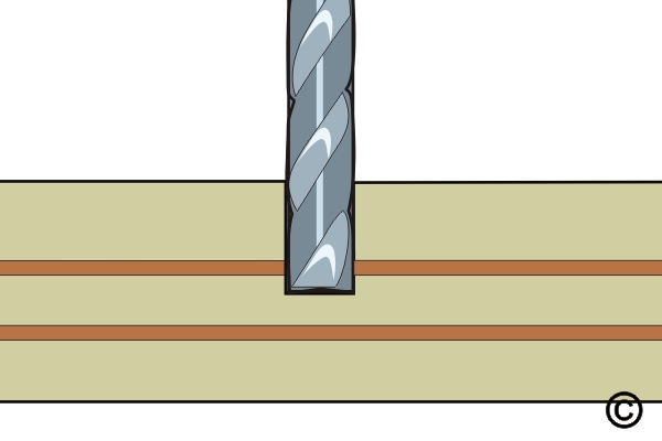
This method is used to sever a circuit or short. A small section of the circuit is removed, forming a break. The width of the break should be at least as wide as the minimum conductor spacing. The Precision Drill System is used with a carbide end mill. This method is recommended for surface or inner layer circuit cuts. After milling, the area is sealed with epoxy.
Note: This method is recommended for surface or inner layer circuit cuts.
Caution: Extreme care must be taken to prevent damage to adjacent or underlying inner layer circuits. A microscope must be used during milling when extreme accuracy is required.
| Procedure References | |
| 1-0 | 1.0 Foreword |
| 2-1 | 2.1 Handling Electronic Assemblies |
| 2-2 | 2.2 Cleaning Procedures |
| 2-7 | 2.7 Epoxy Mixing and Handling |

Ball mills, abrasives and cutting tools for working on circuit boards. |

Clear, superior strength epoxy in two-compartment plastic packages. |

General purpose cleaner for removing contamination. |

One part, semi-paste ink used to tint the color of epoxy and for direct printing on circuit board surfaces. |

Meter and probes to test for electrical continuity. |

Designed for end cutting and hole boring. |

Sturdy rack for PCBs used for rework and positioning. |

High temperature polyimide tape discs, .50" diameter. |

Versatile power tool for milling, drilling, grinding, cutting and sanding. |

Precision microscope with stand and lighting for work and inspection. |

General purpose oven for drying, baking and curing epoxies. |

Precision drill press for accuracy and controlled depth drilling. |

Nine precision-crafted tools for detailed circuit board work. |

Nonabrasive, low-linting wipes for cleanup. |
Procedure
Evaluation