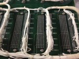
A major manufacturer was looking to remove and replace five 170-pin through-hole connectors on several multi-layer backplane circuit boards. Naturally, there was a need to avoid burning the baseboard surface or damaging to the plated holes. This was a challenging task. See image 1.
Due to the many power and ground planes, the heating process needed to achieve reflow was complex. The challenge was further complicated due to the need to avoid overheating the many jumpers wires adjacent to the connector sites.
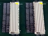
Normally you might first remove the wires, but that step would have added significantly to the rework process time so the wires needed to remain in place during the reflow process. See image 2.
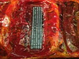
The first step involved protecting the heat-sensitive areas and base board. This was done with a combination of heat shield blankets, heat shield plates and heat shield mask. These components were encased in an additional layer of high temperature tape. See image 3.
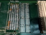
With the prep steps completed, the connectors were reliably removed using a solder fountain system. After the connector removal, each plated hole was cleared of the residual solder using a vacuum desoldering system.
Installation of the replacement connectors was also completed using the solder fountain system. Key to this project was the use of the heat shielding materials used to protect the circuit board surface, and especially the adjacent wires.