While soldering remains one of the oldest and most widely used methods for joining components, hand soldering continues to rely heavily on operator skill. Despite increasing levels of automation in soldering and rework, defects remain an unavoidable reality in mass soldering processes.
Improper solder joints, often caused by inconsistent hand techniques or flawed rework procedures, lead to equipment failures. Therefore, adopting proven, low-stress soldering techniques that deliver high-quality and repeatable results remains critical to achieving reliability.
Various factors influence the effectiveness of hand soldering, including flux application, wetting behavior, temperature control, tip geometry, thermal mass, thermal coupling, and overall technique. With careful attention and occasional process innovation, many soldering challenges can be overcome.
Fine-Pitch Gull-Wing Soldering Procedure
For gull-wing leaded components with fine-pitch terminations, the following step-by-step method provides consistent and controlled solder joints:
- Pad Preparation
Clean all pads thoroughly and apply a thin layer of liquid flux, focusing on the corner pads.
- Component Placement
Accurately align and place the component on the board.
- Tack Soldering
Secure the component by applying the soldering iron tip to the lead-pad junction at one corner. Allow the solder to solidify before proceeding to the opposite corner.
- Solder Preparation
Place a length of small-diameter solder along the edge of the component leads.
- Sequential Soldering
Touch the soldering iron to the solder and the first lead. As the solder melts, it will flow uniformly. Continue this process across the component side, one lead at a time.
This approach ensures precise solder volume and consistent joint formation with minimal thermal stress.
Auxiliary Heat Desoldering Technique
Desoldering through-hole components on high-thermal-mass boards, such as multilayer PCBs, often requires auxiliary heat. This method enhances solder removal efficiency and reduces damage risk:
- Flux Application
Apply liquid flux to the target solder joints.
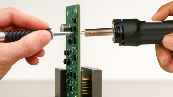
- Dual Heat Setup
Position a soldering iron tip against the component lead on the component side of the PCB. (See Figure 1)
- Desoldering
Align the desoldering tip on the solder side. Once the solder melts, use a slight oscillating motion.
- Vacuum Activation
When resistance decreases (indicating full liquefaction), engage the vacuum to extract the solder.
- Component Removal
Use a staggered approach to desolder the remaining leads, reducing localized heat buildup. Afterward, check each lead to ensure full release before removing the component.
BGA Dog Bone Pad Masking
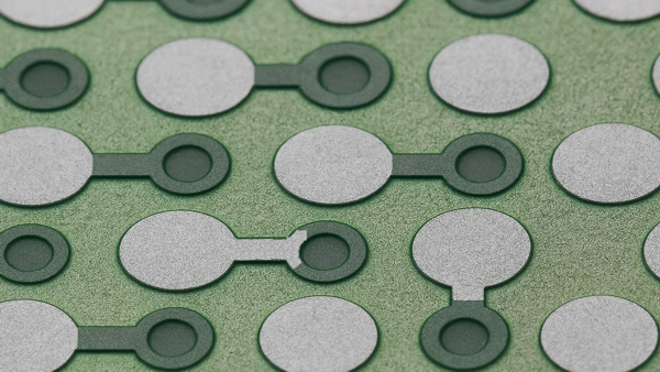
BGA rework presents unique challenges, particularly in terms of solder volume control. In original board fabrication, solder masks between BGA pads and their connecting vias (dog bones) act as dams, preventing solder from wicking into the via. When this barrier is compromised, it must be re-established:
- Inspection
Using magnification, inspect each dog bone to determine if the solder mask needs repair. (See Figure 1)
- Surface Preparation
Carefully remove residual solder and any lifted or damaged mask between the pad and via.
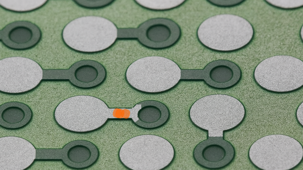
- Dog Bone Preparation
Gently scrape away any solder tinning on the dogbone circuit to provide a better bonding surface for the solder mask or epoxy. (See Figure 3)
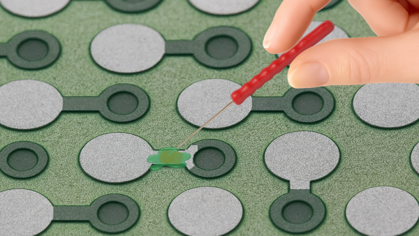
- Epoxy Sealing
Apply high-strength epoxy to seal the exposed copper trace. (See Figure 4)
- Process Continuation
Once the epoxy cures, proceed with BGA placement and reflow, confident that solder will remain confined to the pad area.
Conclusion
While automation reduces some soldering variability, hand techniques remain essential, especially in rework. By applying structured, proven methods and carefully managing heat, solder flow, and pad preparation, technicians can ensure durable, high-quality results that meet industry standards for reliability and performance.
Several members of the Circuit Technology Center team contributed to this feature story. Images may be altered or recreated to protect proprietary information.