Outline
This procedure is followed at Circuit Technology Center for BGA component assembly or rework. The procedure includes receiving, process development, BGA assembly, and BGA rework process steps. The purpose is to ensure repeatable, high-quality assembly and rework of BGA components and to assure conformity to the highest industry standards and specifications.
Minimum Skill Level - Advanced
Recommended for technicians with soldering and component rework skills and exposure to most repair/rework procedures, but lacking extensive experience.
Conformance Level - High
This procedure most closely duplicates the physical characteristics of the original, and most probably complies with all the functional, environmental and serviceability factors.
Kits and Systems
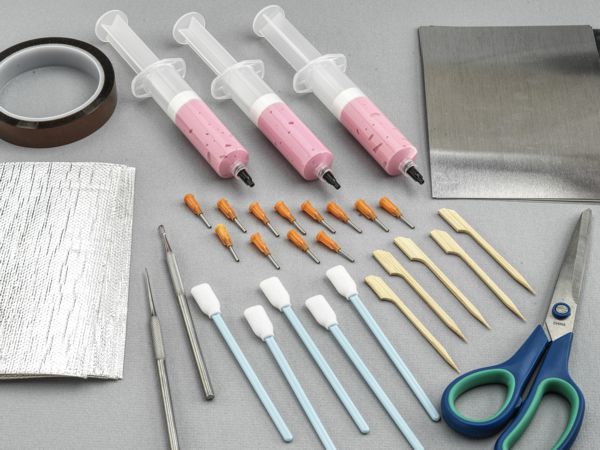
Heat Shield Kit
Kit includes tools and materials needed to protect heat sensitive area of a circuit board during rework.
Precision Tool Set
Nine precision-crafted tools for detailed circuit board work.
Additional Items and Supplies
BGA Rework System
Hot air or infrared BGA component rework system.
Cleaner
General purpose cleaner for removing contamination.
Hot Air Tool
Tool and nozzles to deliver precise flow of hot air.
Microscope
Precision microscope with stand and lighting for work and inspection.
Oven
General purpose oven for drying, baking and curing epoxies.
Soldering Iron
Properly maintained soldering iron and properly sized soldering iron tips.
Wipes
Nonabrasive, low-linting wipes for cleanup.
Heat Shield
During component rework, protection of nearby components is often mandatory to avoid collateral heat damage or inadvertent reflow. Collateral heat damage or unintended reflow of adjacent component solder connections can result in component damage, oxidation, de-wetting, pad damage, wicking, starved joints, and scorching. The rework technician must constantly be aware of the effect of heat on the target device or circuit, plus how it affects components near the target device on both sides of the assembly.
235-4010 Heat Shield Blanket
These are 5" x 7" sheets of fiberglass fabric, aluminum foil laminate with a pressure-sensitive adhesive backing. Heat Shield Blanket is designed to reflect 90% of the radiant heat energy. It will withstand continuous heat in the leaded and lead-free solder melt temperature range and short-term exposure at temperatures up to 1000°F/538°C. Heat Shield Blankets can be used in conjunction with Heat Shield Plates to create a more robust thermal shield with a more rigid structure.
235-4060 Heat Shield Plates
These are light gauge 5" x 7" aluminum sheets used primarily when simple heat deflection is required. Heat Shield Plates are easy to size, cut, form, and bond or tape into place using the high-temperature mask or high-temperature tape supplied in the kit. When using Heat Shield Plate material to deflect heat, leave a small space between the Heat Shield Plate and the protected component or area to avoid direct contact transfer of heat.
115-9010 Mask, High Temperature
This product is a high-temperature, quick cure, synthetic latex, peel-able solder mask supplied in syringes with dispensing needles. This mask can create free-form heat shielding or seal the edges of the Heat Shield Blanket or Heat Shield Plates. This mask cures at room temperature in 5 minutes. Once dried, it can be peeled off after use.
Images and Figures
Plastic Ball Grid Array Component
Figure 1: Commercially available BGA Rework Station.
Caution - Operator Safety: A thorough review of the equipment manual and comprehensive training is mandatory. Daily maintenance is essential. Consult the equipment manual for more information.
Caution - Component Sensitivity: This method may subject the component to extreme temperatures. Evaluate the component's tolerance to heat prior to using this method. Plastic BGA components are especially sensitive to moisture absorption. Carefully evaluate pre-bake requirements.
Caution - Circuit Board Sensitivity: PC Boards are made from a great variety of materials. When subjected to high temperatures, they are susceptible to the following types of damage:
Layer delamination.
Copper delamination, separation of pads, barrels of inner layers.,/li>
Burns and solder mask chipping.
Warp.
Each circuit board must be treated individually and scrutinized carefully for its reaction to heat. If a series of circuit boards are to be reworked, the first several should be handled with extreme care until a reliable procedure is established.
Receiving and Price Quoting
Upon receipt, the customer-supplied materials and products are logged into the Enterprise Resource Management System by the Shipper & Receiver. Customer-supplied materials and product counts are verified.
The project is reviewed by the appropriate Sales Application Engineer to confirm the project requirements, determine the solder chemistry classification, and verify if a solder stencil is in stock or needs to be ordered. Repeat projects will have a previously created process sheet in the Customer Process Specification database. A copy is printed and included with the job Traveler.
New projects require a thermal profile for the circuit board. See the process step listed below and procedure 9.2.1. For profile development, we request a scrap circuit board assembly and extra components whenever possible.
Upon completion of the Sales Order, it is sent via email to the customer contact for confirmation of the process outlined and the charges listed. The schedule is confirmed, and the customer products and materials are transferred to the BGA rework area.
Project Process Development
Prior to starting the project the Operator will review the following:
A. Verify that circuit board, and component part numbers and quantities match the Traveler.
B. Visually inspect the circuit boards for temperature-sensitive components or parts. (Fiber optics, plastic connectors, batteries, etc.)
C. Ensure the BGA machine maintenance is current and the appropriate checks are done prior to operating the BGA machines.
All Circuit boards are baked for a minimum of 12 hours at 125 C unless otherwise instructed by the customer. In addition, all BGA components that are received in unsealed packaging are baked per the Moisture Sensitive Device Control Procedure unless otherwise instructed by the customer.
Thermal Profile development is required for all projects. If available, the Operator will develop the thermal profile using a customer-supplied scrap assembly that is the same as the circuit boards to be processed. If the customer is unable to supply a scrap board, the thermal profile is developed during the initial removal process. In both cases, the operator will identify the following board conditions and start with the most logical machine setting:
A. Solder chemistry, leaded or lead-free.
B. Board thickness.
C. Board and component density and layout.
D. Component ball count and design.
E. Under-fill or conformal coating surrounding the site.
The thermal profile is created by placing thermocouples at various locations to monitor and adjust the heating source time and temperature from the bottom side heat plate and the top side nozzle. Multiple machine cycles may be required to achieve the desired results. Upon completion, the profile is stored in the machine and saved in the Customer Process Specification database for current and future applications. See procedure 9.2.1 for more detailed information.
Additional notes are added to the Customer Process Specification to identify special handling or other process steps that are needed in order to achieve an acceptable condition. These include adjacent components that need removal, specific masking or shielding requirements, and other conditions that may impact the process.
BGA Rework Process
Operators initially review the Traveler and additional paperwork to ensure the instructions are clear and match the circuit boards to be processed. Any questions are directed to the Sales Application Engineer or to the customer for clarification.
If circuit board disassembly is needed, all materials must be labeled and noted on the Traveler.
The operator will locate and load the removal profile specified on or with the Traveler for the component removal. The removal process is visually monitored through a microscope. When the BGA component solder balls reach a molten state, the vacuum pick-up of the component is initiated.
Site cleaning is done with a non-contact site cleaning tool or by using solder wick. If under-fill or conformal coating is present at the site, additional steps are required to remove it. Typically heat, machining or chemical stripping of the site is needed. Refer to the Sales Application Engineer, customer instruction, or the product data sheet for the appropriate process.
No-clean solder paste or flux is utilized for BGA assembly and rework unless otherwise instructed by the customer.
After the site cleaning process is complete, the circuit board is inspected to ensure the mask is undisturbed and the site is suitable for the installation process. If solder mask touch-ups or other issues are identified, they are reviewed with the Sales Application Engineer for direction.
Solder stencils are used to deposit the solder paste onto the site. Care is taken to ensure the paste is deposited evenly and completely.
The installation of the BGA component is completed following the programmed profile specified on or with the Traveler. The installation process is visually monitored through a microscope, and when the BGA component solder balls and solder paste reach a molten state and ball collapse is confirmed, the placement process is complete.
Note: High-temperature solder balls will not collapse and will rely on the paste wetting to the ball.
Upon completion of the placement process, the circuit board is visually inspected at the BGA placement site and all adjacent areas. Touch-up of the circuit board is completed if needed.
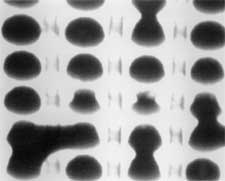
X-ray inspection is completed at the BGA placement site and adjacent areas. See procedure 9.1.2 for additional information. Any potential workmanship or unacceptable conditions are reviewed with the Sales Application Engineer for direction.
Re-assembly of any removed components or hardware is performed.