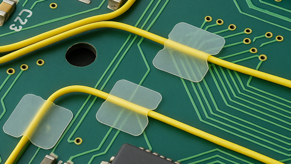
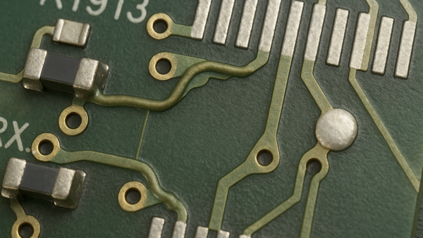
6.2.2 Jumper Wires, BGA Components, Through Board Method
Route jumper wires at BGA sites using through-board techniques to restore connectivity. Includes drilling, wire insertion and termination methods for secure, reliable repairs.
Minimum Skill Level: Expert
Conformance Level: High
REQUEST FOR QUOTE GUIDES INDEX