Outline
This method is used to repair damaged and lifted lands. The lifted lands are repaired with dry film epoxy. They are re-bonded to the circuit board surface using a bonding press or bonding iron.
Caution: It is essential that the board surface be extremely smooth and flat. If the baseboard is damaged, see the appropriate procedure.
Minimum Skill Level - Advanced
Recommended for technicians with soldering and component rework skills and exposure to most repair/rework procedures, but lacking extensive experience.
Conformance Level - Medium
This procedure may have some variance with the physical character of the original and most likely varies with some of the functional, environmental and serviceability factors.
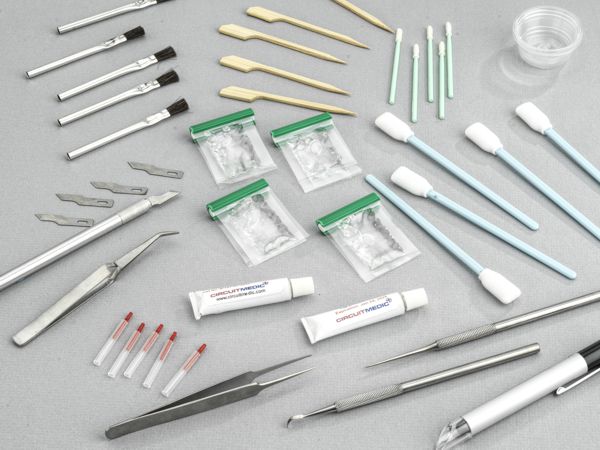
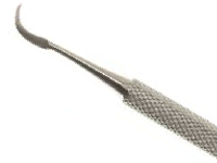
Scraper, Curved Tip
Hardened stainless steel tip for scraping solder mask and removing defects.
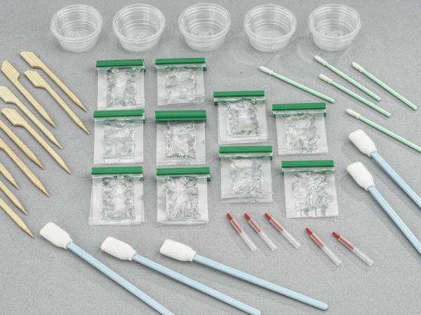
Additional Items and Supplies
Cleaner
General purpose cleaner for removing contamination.
Microscope
Precision microscope with stand and lighting for work and inspection.
Tweezers
Multiple sizes and tip configurations of tweezers for various small parts handling needs.
Wipes
Nonabrasive, low-linting wipes for cleanup.
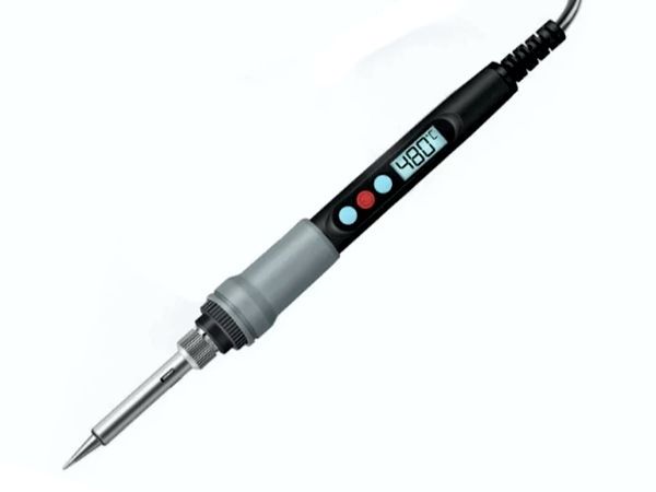
Bonding Iron Tips
Bonding Iron Tips fit into the handheld Bonding Iron. The bottom surface of each Bonding Tip is used to apply heat and pressure to bond adhesive-backed replacement lands, pads, and edge contacts to a circuit board surface. The pressure/force listed is the recommended load in pounds to apply to the top surface of the replacement adhesive-backed pads, lands, and conductors. The load is based on the Bonding Tip surface area to meet the recommended load for Circuit Frames at 200 - 400 psi.
Figure 1: Cut out the appropriate shape of Bonding Film material to match the area of the lifted land.
Figure 2: Place Kapton tape over the lifted land.
Figure 3: Bond the land using a Bonding Iron.
Procedure
Clean the area.
Remove any obstructions that prevent the lifted land from making contact with the base board material.
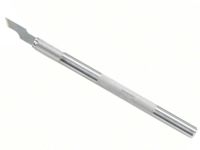
Use the Surgical Knife and scrape off any epoxy residue, contamination, or burned material from the board surface.
Clean the area.
Cut out a piece of bonding film that matches the area of the lifted land. Be careful not to contaminate the dry film epoxy with materials that could reduce the bond strength. (See Figure 1)
Note: Dry film adhesive thickness should be selected to meet the requirements of the PC Board.
Place the dry film under the lifted land. (See Figure 1)
Place a piece of High-Temperature Tape over the lifted land and press the land down into contact with the adhesive film. (See Figure 2)
Select a bonding tip with a shape to match the shape of the lifted land.
Note: The bonding tip should be as small as possible but should completely cover the entire surface of the new land.
Position the circuit board so that it is flat and stable. Gently place the hot bonding tip onto the tape covering the new land. Apply pressure as recommended in the manual of the repair system or repair kit for 5 seconds to tack the land in place. Carefully peel off the tape. (See Figure 3)
Gently place the bonding tip directly onto the land. Apply pressure as recommended in the manual of the repair system or repair kit for an additional 30 seconds to fully bond the land. The bonding film is fully cured. After the bonding cycle, remove the tape used for alignment. Carefully clean the area and inspect the land.
Note: Double-sided and multilayer circuit boards may require an eyelet to restore the through connection. Refer to section 5.0 Plated Hole Procedures.
Carefully remove any excess bonding film inside the plated hole using a ball mill or drill bit. Turn the ball mill or drill bit by hand to prevent damage to the wall of the plated through hole.
Install the proper component and solder in place.
Note; This method is used to repair a lifted land, but the repaired land may not have an intermetallic connection to the remaining plated hole. The solder joint of the replaced component will restore the integrity of the electrical connection, or an eyelet or buss wire may be used. See Plated Hole Repair Procedures.
Replace surface coating to match prior coating as required.
Evaluation
Visual examination and tape test per IPC-TM-650 test method 2.4.1. (ANCI/IPC-FC-250A)