Tips For Through Hole Connector Rework
|

|
|
|
Figure 1: Typical solder fountain system used to quickly and reliably remove and replace large through hole components, including connectors.
|
Consider a typical scenario where a project is already overdue and you learn that a 150-pin connector needs to be replaced. Desoldering the connector one pin at a time using vacuum desoldering tools just won't cut it.
Quickly removing and replacing a large multi-pin connector seems a daunting task, but it really isn't. Here's how it can be done.
The solution, and likely the best method, is to reflow all the solder joints at once using a solder fountain system. This enables you to remove and replace the connector in two quick operations.
A solder fountain system generates significant heat, with molten solder in direct contact with the board. This is what a high-mass object like a connector needs. However, it's important that the dwell over the molten solder be as brief as possible. The number of times that the connections are reflowed should be kept to a minimum to protect the board, the components, and the solderability of surfaces.
|
|
|
Figure 2: Connector aligned directly over the flowing molten solder.
|
The operator needs to exercise extra caution. This process uses molten solder and exposes the untrained operator to serious hazards. A thorough review of the solder fountain system and comprehensive training is mandatory.
Solder Fountain System
Most solder fountain systems have the same basic components. These include a solder pump and solder reservoir, interchangeable nozzles in various sizes, and controls for solder fountain height. Solder from the reservoir is driven up through the nozzle by the pump.
Above the solder fountain head, there is generally a light projected alignment mark that permits you to center the part to be removed over the nozzle. (See Figure 1)

|
|
|
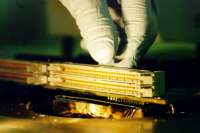
Figure 3: Once full solder reflow has been achieved, remove the connector either by hand, or with an extractor tool.
|
Ideally, the leads of a component should be immersed in the molten solder without having the solder wave exert any upward pressure on the circuit board. (See Figure 2)
Insufficient immersion in the solder wave will prevent proper heat transfer and reflow. Excess pressure will cause the solder to surge up through holes and to spill out onto the top side of the circuit board.
There are a variety of removal tools to help extract the component once reflow has been achieved.
Circuit Board Preparation
If components, or the circuit board surface, are susceptible to damage or exposure to solder, they must be protected. This can be done by applying high-temperature tape to any flat surfaces surrounding the rework area or applying a high-temperature flexible mask to protect irregular surfaces. The mask may need baking to properly cure prior to reflow.
Pre-bake
Circuit boards should be baked for 1 to 4 hours at 65 degrees C - 120 degrees C. Time and temperature requirements for pre-heat depend on board construction, age, exposure, and moisture sensitivity specifications.
Baking will drive out moisture from the circuit board to prevent delamination, reduce thermal shock to the board that may cause surface or internal damage, and raise the temperature of the circuit board and components to allow for quicker component removal.
Removal Procedure
- Set up the solder fountain system and install the proper nozzle. Check the table height and solder wave height to be sure they are properly set for the circuit board.
- Apply liquid flux to both the top and bottom side solder fillets of all the leads of the connector to be removed.
- Place the circuit board over the nozzle. (See Figure 2) Check the position using the alignment light and activate the solder fountain. Once full solder reflow has been achieved, remove the connector either by hand or with an extractor tool. (See Figure 3) Immediately drop the solder fountain to prevent overexposure. Operator skill and experience are required to prevent hole and pad damage caused by premature removal of the connector, or from heat damage due to delayed removal.
- Allow the circuit board to cool before cleaning and inspection.
Replacement Procedure
- Preform connector leads if needed, and test on a practice board to be sure leads are properly aligned.
- Set up the solder fountain system and install the proper nozzle. Check the table height and solder wave height to be sure they are properly set for the circuit board.
- Apply liquid flux to both the top and bottom sides of all the solder-filled holes and to the leads of the connector.
- Place the circuit board over the nozzle. Check the position using the alignment light and activate the solder fountain. Once full solder reflow has been achieved, insert the new connector. Immediately drop the solder fountain wave to prevent overexposure. A great deal of operator skill and experience are required to expect good results when inserting the connector during the solder fountain cycle.
- Allow the circuit board to cool before cleaning and inspection.
Several members of the Circuit Technology Center team contributed to this feature story.
|
|
|
|
|