BGA rework is a topic about which volumes have been written, and in most cases, the focus has been on component removal and replacement. However, equally important is the topic of BGA site modification, and the need for such modification often arises.
A common type of BGA site modification is the need to add a jumper wire at a BGA site. One option is to run a jumper through a hole in the board. This method is typically used for engineering changes and modifications.
This method is used when there is a buried via, and other methods of terminating to the opposite side are not an option. This method also requires a high degree of operator skill and precision milling equipment. It's fairly complex and must be done correctly to ensure a robust and reliable result.
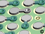
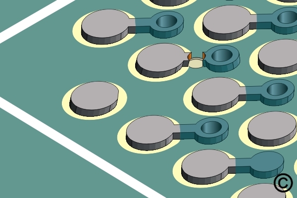
Figure 1: Drill though the board and insert a Teflon sleeve into the milled hole. This sleeve will insulate the new conductor and prevent shorting to the inner layers.
The procedure begins with removing the BGA component and surface solder, followed by site cleanup and inspection. If all is well, the next step is to remove the solder mask from the via pad terminating to the subject BGA pad.
Mill a hole through the board at the precise coordinates using a precision drill system and end mill of the appropriate size. Although both power and ground planes may be cut, cutting inner layer signal traces must be avoided. Inspect and clean the area.
Next, insert an appropriately sized Teflon sleeve into the milled hole. This sleeve will insulate the new conductor and prevent shorting to the inner layers. (See Figure 1).
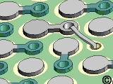
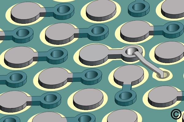
Figure 2: Insert one end of the circuit track into the plated hole or via connected to the BGA pad. Then insert the opposite end through the Teflon sleeve.
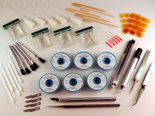
Select a flat, ribbon-shaped, circuit track that will be inserted through the Teflon sleeved hole. These pure copper replacement circuit tracks are available in many sizes. A typical size for this application may be .003" thick by .015" wide. The ends of the circuit track may be tinned with solder prior to the next step.
Now, insert one end of the circuit track into the plated hole or via connected to the BGA pad. Then insert the opposite end through the Teflon sleeve. (See Figure 2). Apply a small amount of liquid flux and lap solder the circuit track to the plated hole connected to the BGA pad.
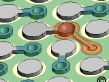
Thoroughly clean the area. Mix some high strength, high-temperature epoxy and coat the top and sides of the new circuit. The epoxy bonds the new circuit to the baseboard material and insulates the circuit. Be sure to keep the epoxy height below the BGA pad level. (See Figure 3).
Figure 3: Mix high strength, high temperature epoxy and coat the top and sides of the new circuit.
Clean the board as required, prep the site, and install the new BGA component. Then, turning to the other side of the board, solder a jumper wire to the exposed circuit track on the opposite side, and route and terminate the jumper wire as needed.
Conclusion
A bit elaborate, but one option to consider when no other is available.
Several members of the Circuit Technology Center team contributed to this feature story.